Hardware installation
Base structure assembly
| Qty | Part ID | Part description |
|---|---|---|
| 1 | H_LP | Left Panel |
| 1 | H_BS | Bottom Structure |
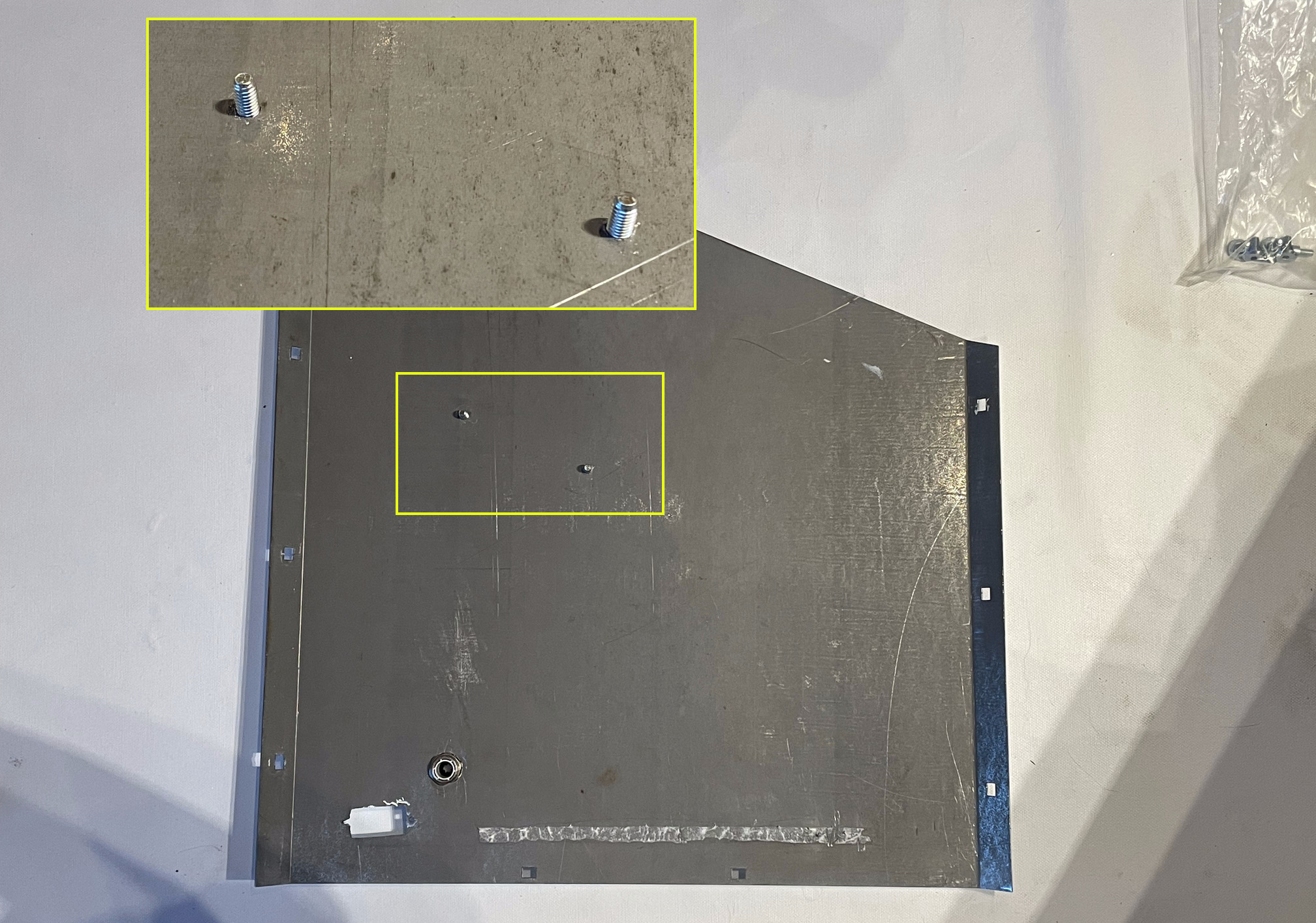
| 1 | H_PLATE | Bottom Plate |
| 1 | P_BR1 | Rail |
| 1 | P_BR2 | Rail |
| 5 | B_FSS_M6_20 | M6 20mm flat head socket screw |
| 4 | B_CB_M6_20 | 6x20mm carriage bolt |
| 4 | B_SS_M4_15 | M4 15mm socket screw |
| 4 | B_SS_M6_20 | M6 20mm socket screw |
| 1 | M_CG | Cable gland |
| 4 | B_W_M6 | M6 flat washer |
| 4 | B_N_M6 | M6 nut |
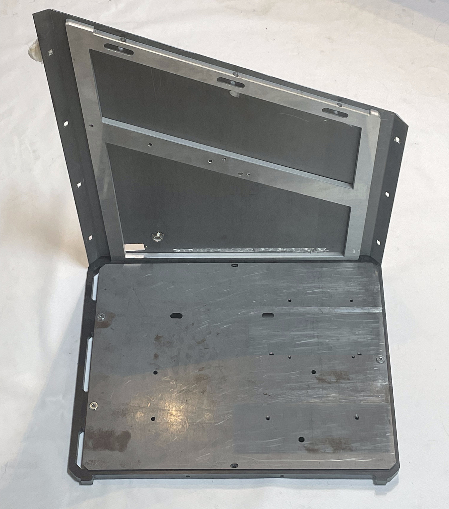
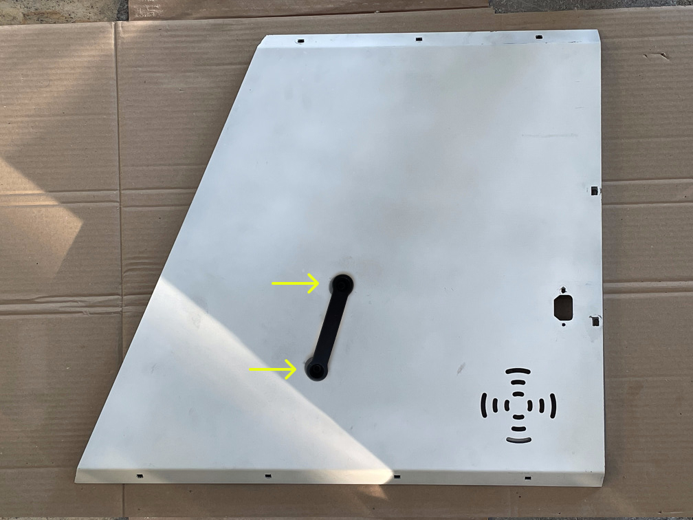
- Attach H_LP to H_LS with 2x B_CB_M6_20, 2x B_W_M6 and 2x B_N_M6.
- Mount M_CG to H_RP.
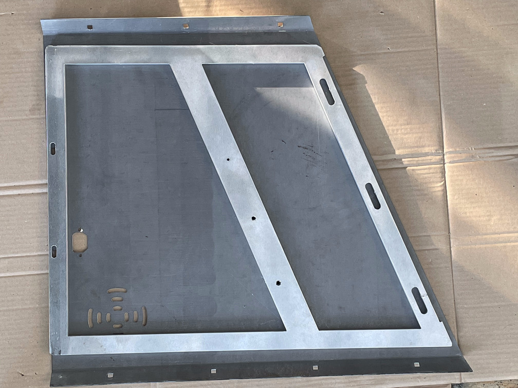
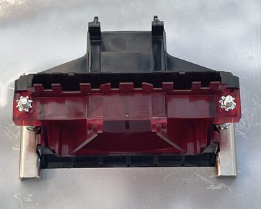
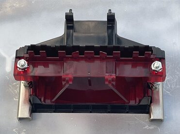
- Assemble the sides with the bottom by screwing 2x B_CB_M6_20 through the bottom of the side panel and H_BS. Make sure to put H_BS in the right direction: the side with the two holes must be on the lowest side of H_LP and H_RP.
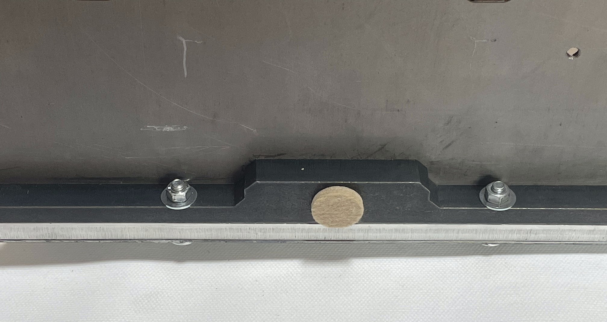
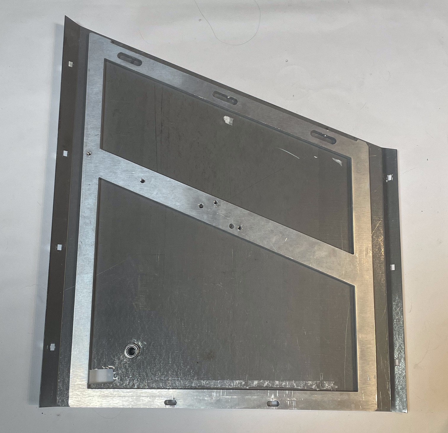
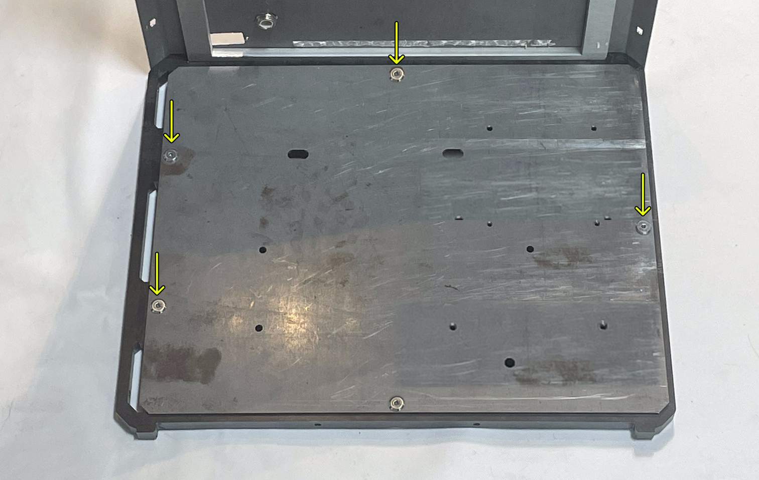
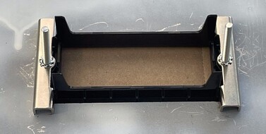
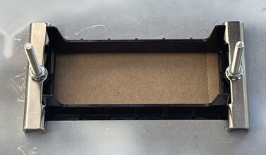
- Attach H_PLATE to H_BS with 5x B_PCB_M6_20. Make sure the plate is oriented as illustrated in the figure.
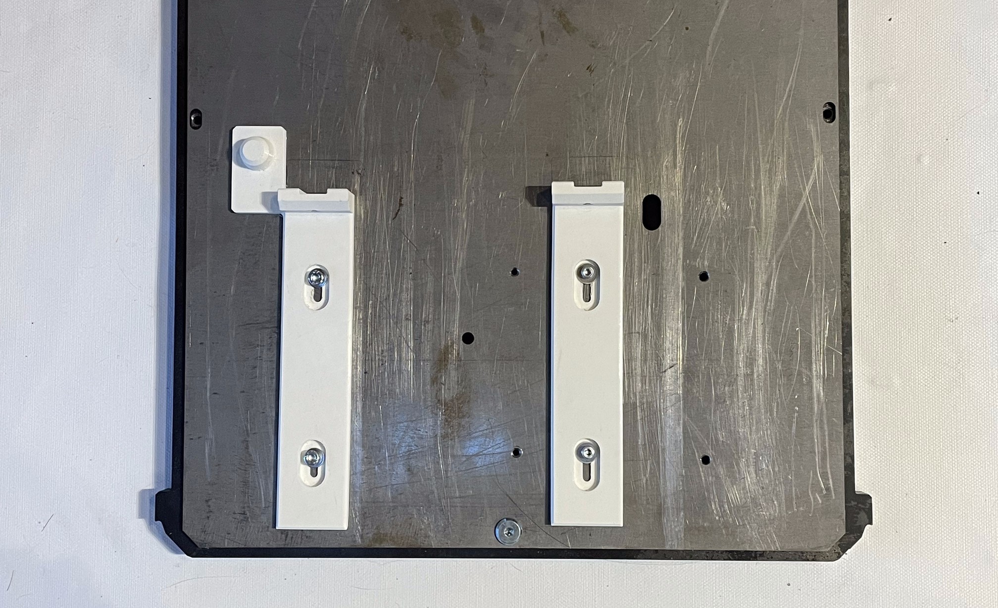
- Attach P_BR2 and P_BR1 to H_PLATE with 4x B_SS_M4_15.
- Attach P_P12C and P_P05C to H_RS with 4x B_SS_M6_20.
Components preparation
Left side component
| Qty | Part ID | Part description |
|---|---|---|
| 1 | H_RS | Right Structure |
| 1 | H_RP | Right Panel |
| 2 | B_CB_M6_20 | 6x20mm carriage bolt |
| 2 | B_W_M6 | M6 flat washer |
| 2 | B_N_M6 | M6 nut |
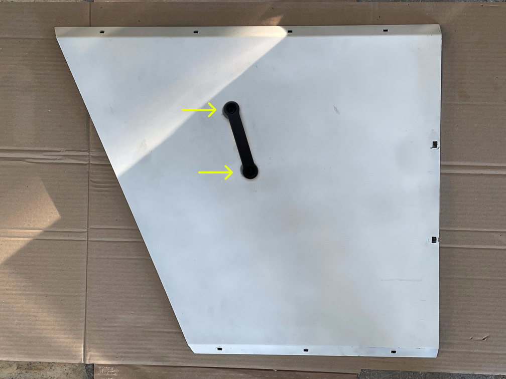
- Attach H_RP to H_RS with 2x B_CB_M6_20, 2x B_W_M6 and 2x B_N_M6.
Front panel component
| Qty | Part ID | Part description |
|---|---|---|
| 1 | M_CL | Metal clamp |
| 1 | H_FP | Front panel |
| 1 | E_CIN | NV10 Cash-in device |
| 1 | M_CINB | NV10 bezel |
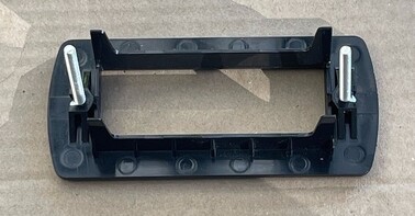
| 1 | M_CINF | NV10 bezel frame |
| 4 | B_N_M3 | M3 nut |
| 2 | B_B_M3_25 | M3 long bolt |
| 4 | B_L_M3 | M3 external tooth lock |
- Clip 2x B_B_M3_25 to M_CINF.
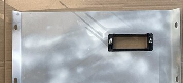
- Pass M_CINF through the rectangle hole at the top of H_FP,
- Pass 2x M_CL to the bolts. Pass 2x B_L_M3 through the bolts.
- Tighten with 2x B_N_M3.
- Pass M_CINB through the bolts. M_CINB must be "smiling" when looking at the painted part of H_FP. Pass 2x B_L_M3 through the bolts.
- Tighten with 2x B_N_M3.
- Insert E_CIN in P_IM_T. Make sure the two rectangles holes of P_IM_T are on the side of the connector on E_CIN. The connector must be aligned with the top hole.
- Attach P_IM_T with P_IM_B with 4x B_W_M4 and 4x B_SS_M4_15.
- Clip Cash-in component on M_CINB mounted on H_FP. To clip it, you need to tilt it down at 45 degrees, pass it through clips and pull it back up horizontally.
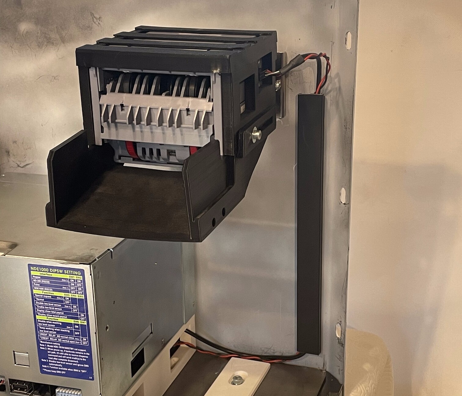
Cashout component
| Qty | Part ID | Part description |
|---|---|---|
| 4 | B_SS_M4_15 | M4 15mm socket screw |
| 4 | B_W_M6 | M6 flat washer |
| 1 | P_OM | NDE-1000 mount |
| 1 | E_COU | NDE-1000 cash-out device |
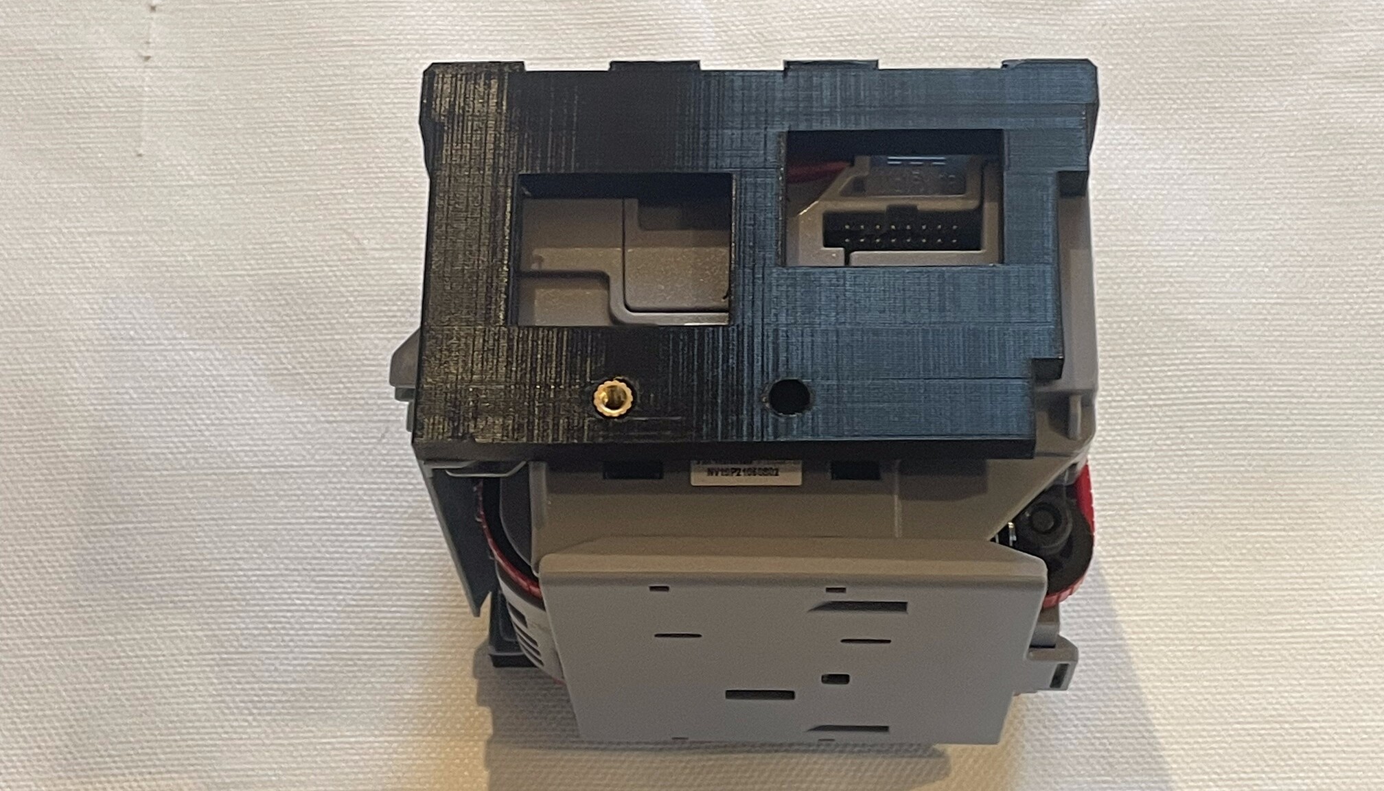
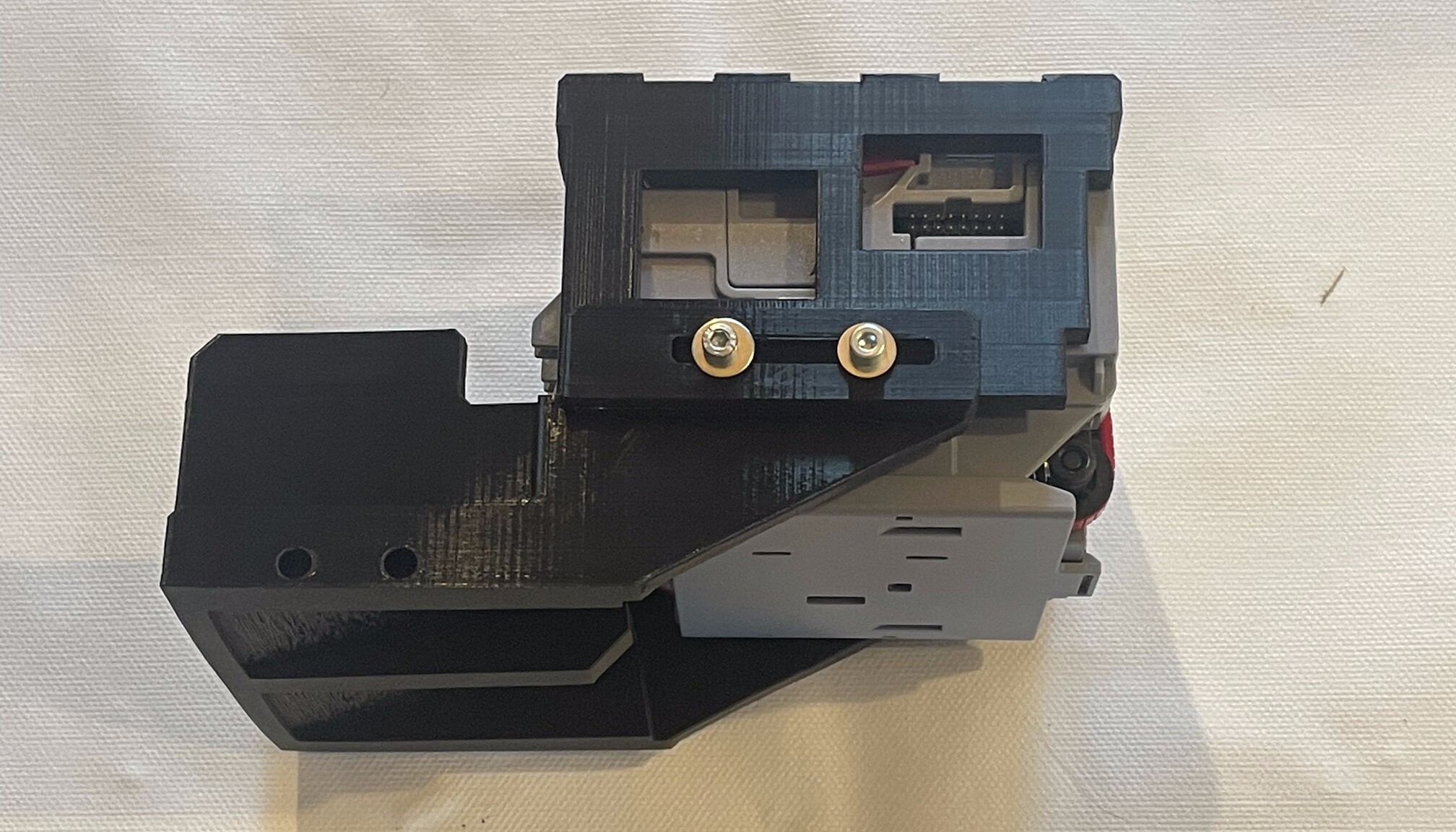
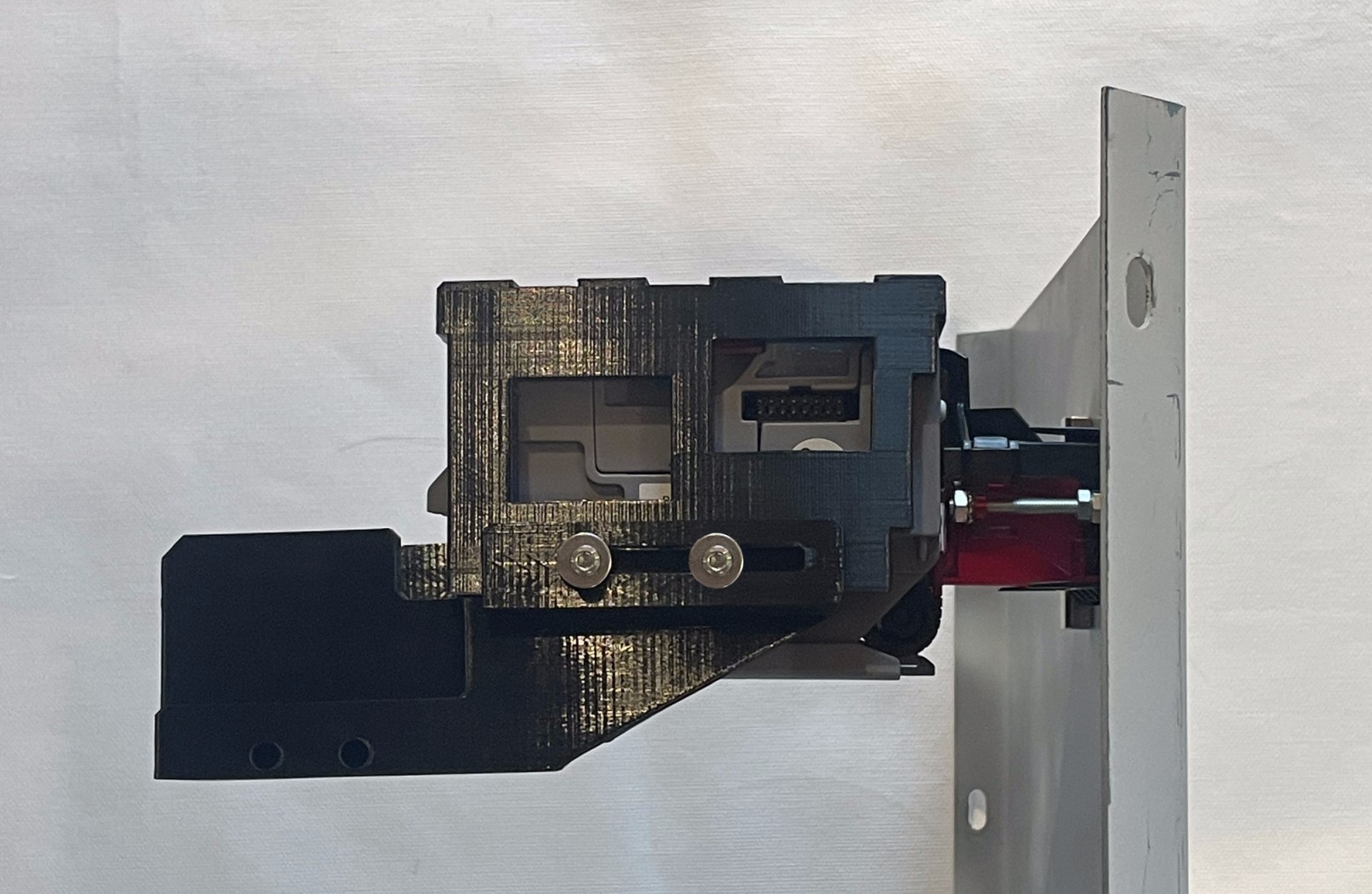
- Attach P_OM to the bottom of E_COU with 4x B_SS_M4_15 and 4x B_W_M6. Make sure to install P_OM accordingly to the figure. P_OM back screw hole must be at the back of NDE-1000.
Top structure component
| Qty | Part ID | Part description |
|---|---|---|
| 1 | H_TS | Metal clamp |
| 1 | P_RC | RPI4 case |
| 1 | B_SS_M3_10 | M3 10mm socket screw |
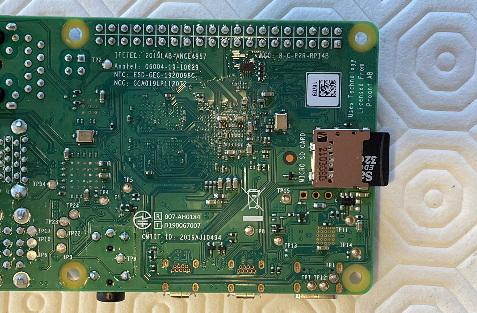
| 1 | E_RPI | Raspberry Pi 4 Model B |
| 1 | E_CAM | 16MP IMX519 Autofocus Camera Module |
- On E_CAM, unplug the camera module from the camera ribbon cable if it is not done already.
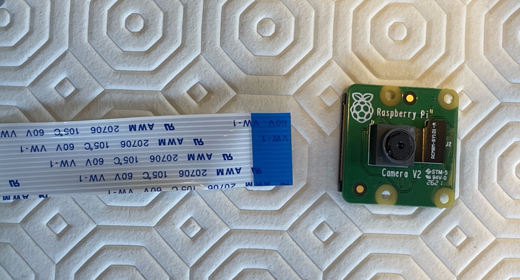
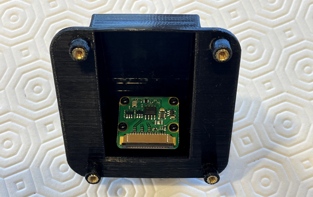
Attach E_CAM module to P_CAC using 4x B_S_1.
Plug E_CAM flat ribbon cable in E_RPI. Make sure that the metal pins on the cable face the pins on E_RPI.
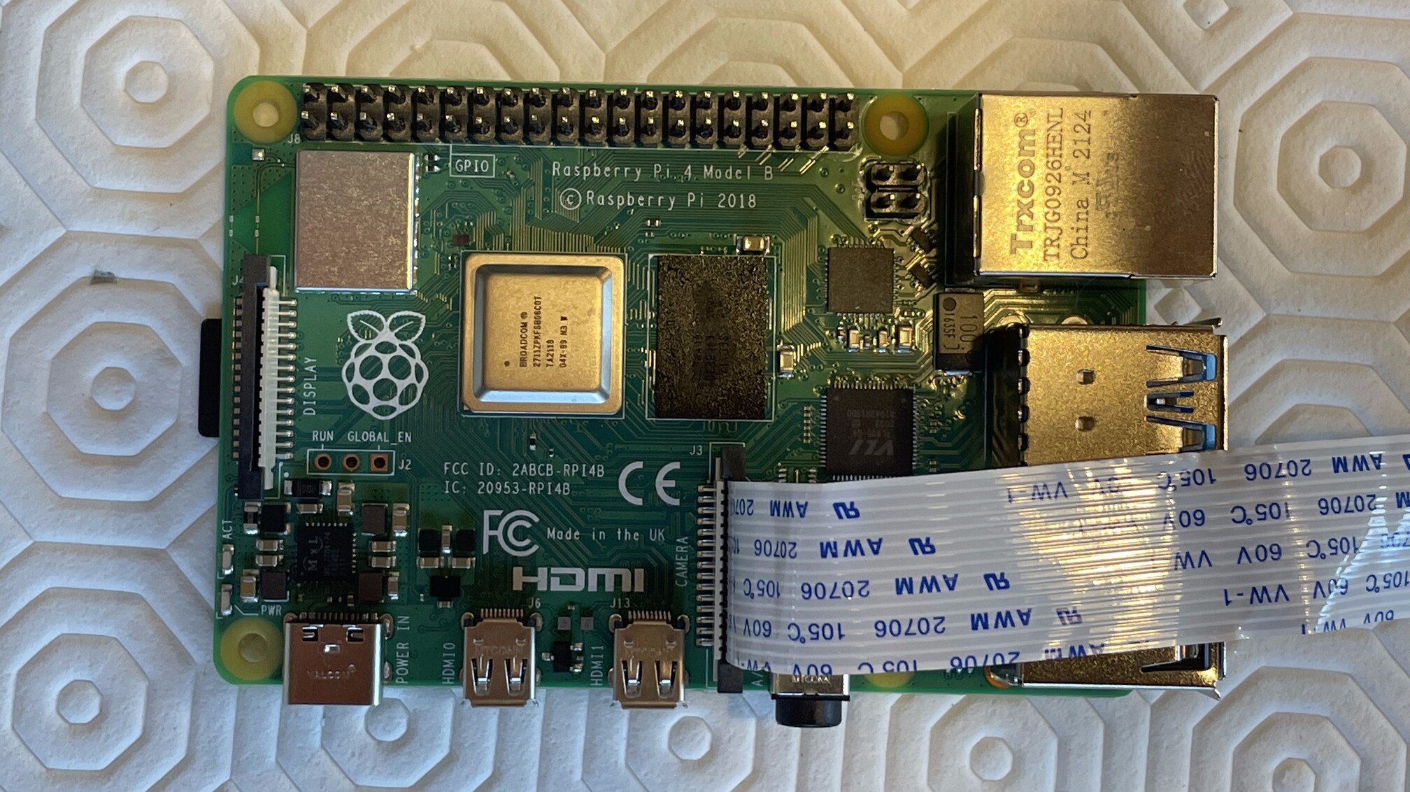
- Insert the included E_SD in the SD card slot on E_RPI.
- Attach P_RC to H_TS with 1x B_SS_M3_10.
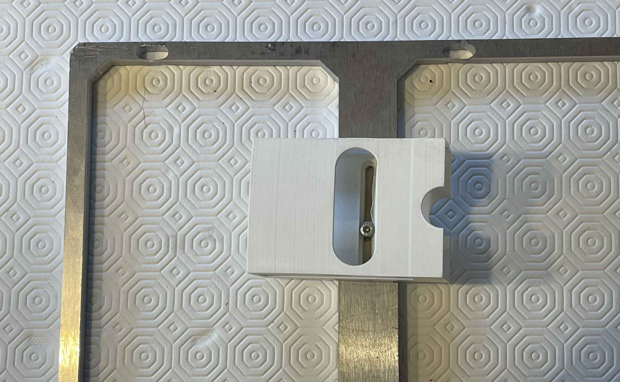
- Insert E_RPI in P_RC. TBD Attach it with 4x bolts.
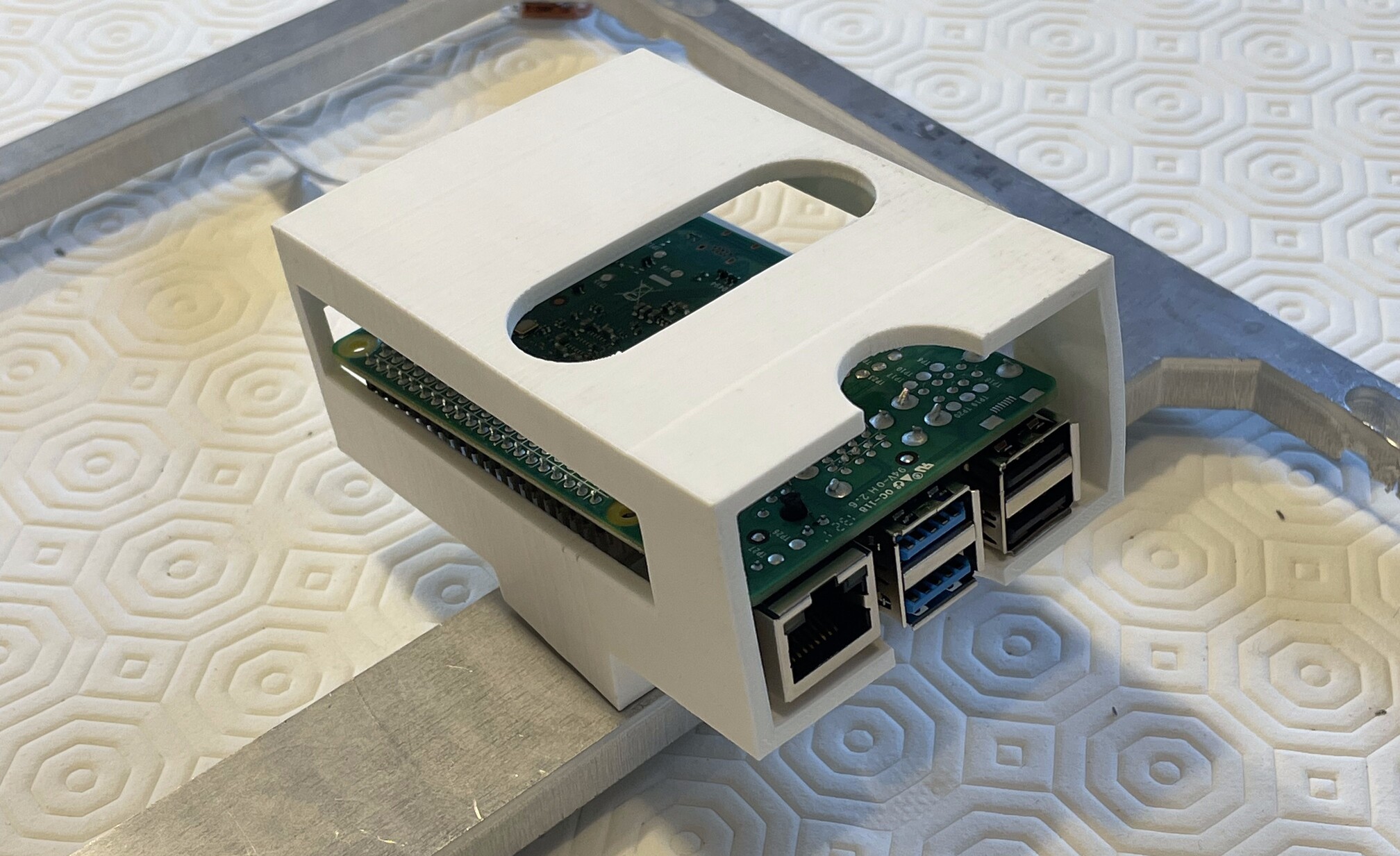
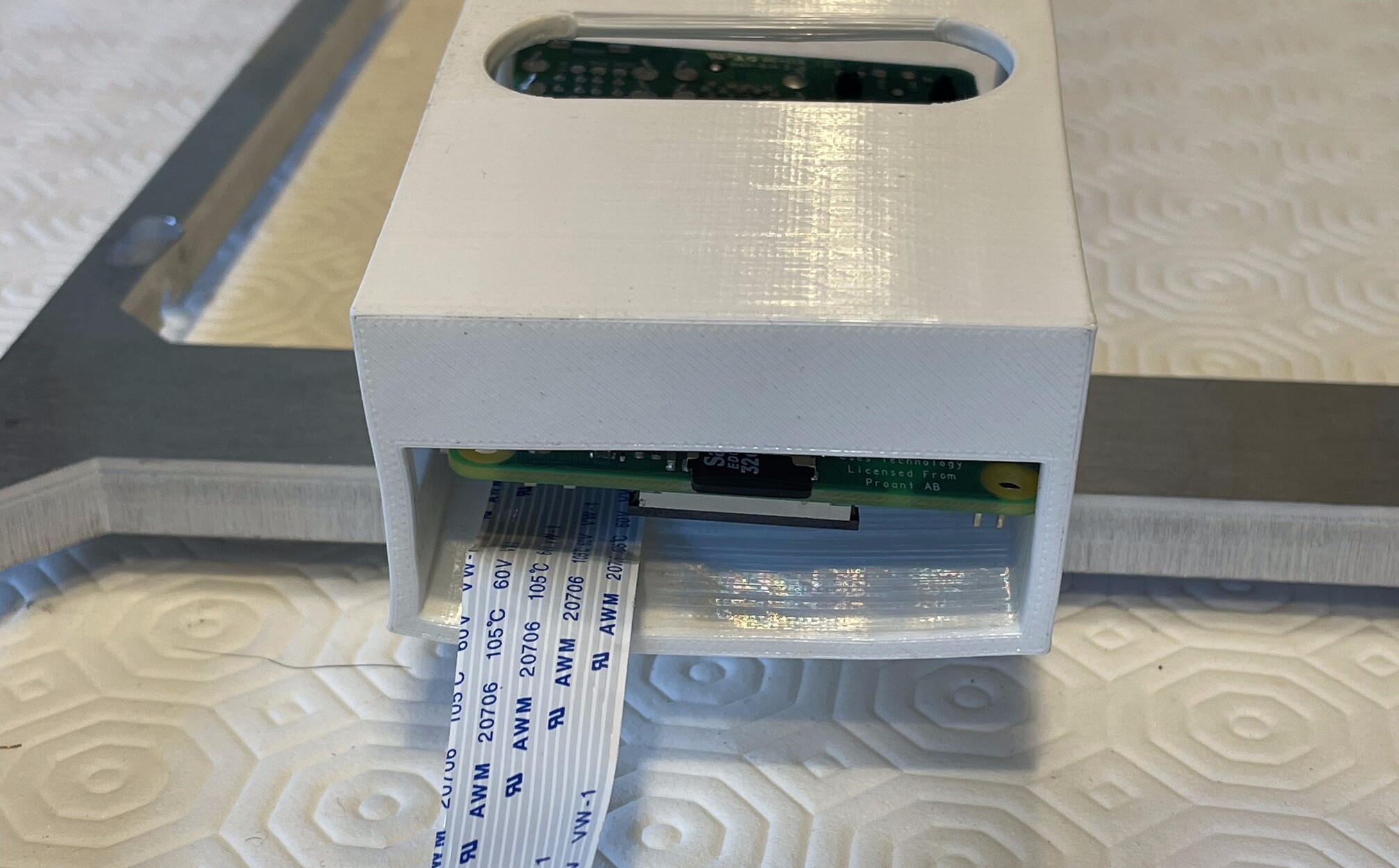
- Pass the camera ribbon cable through the slit at the rear of P_RC.
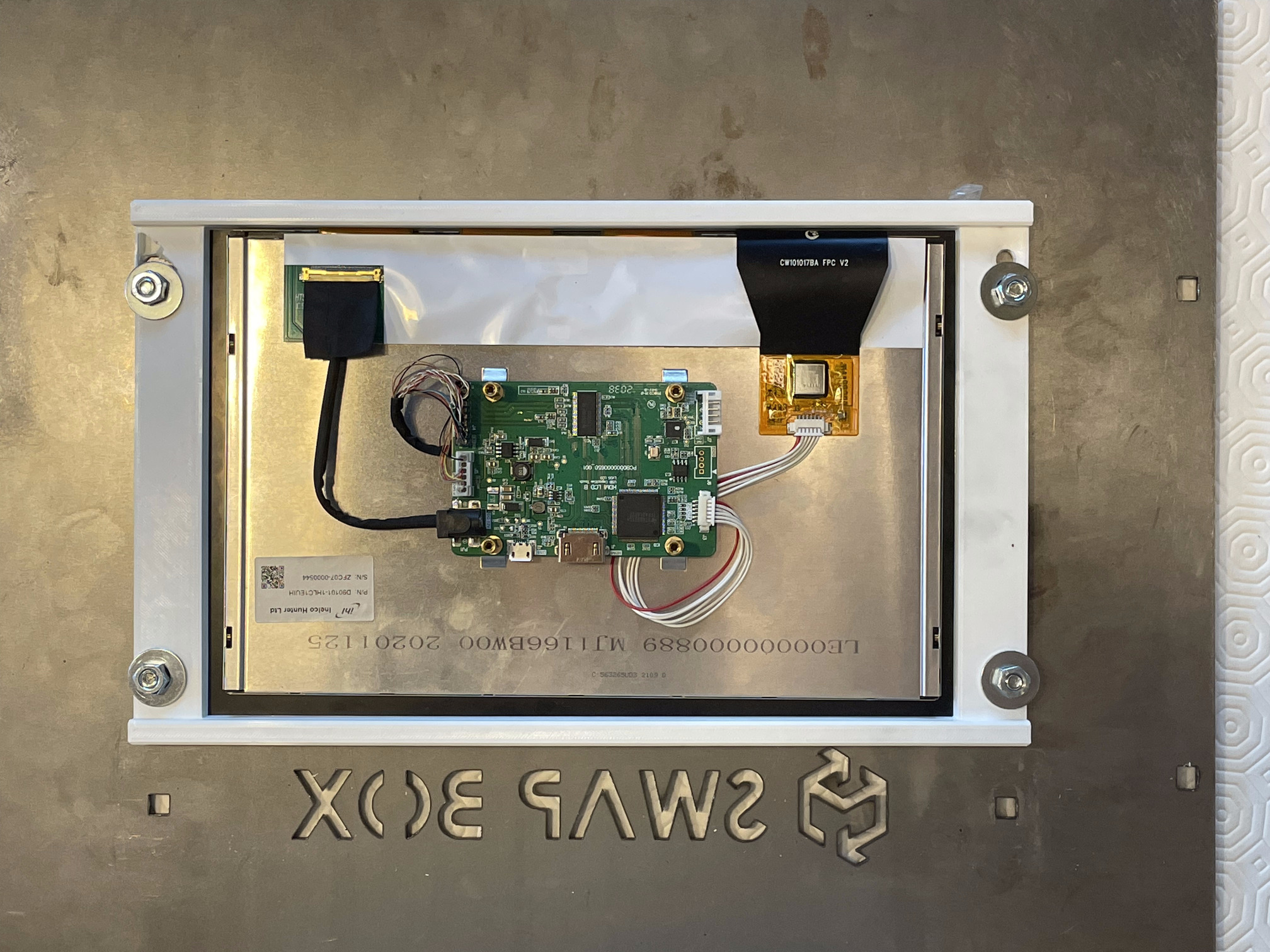
Top panel component
| Qty | Part ID | Part description | Image |
|---|---|---|---|
| 1 | H_TP | B_N_M6 | |
| 1 | E_SCR | 10.1" IPS Industrial Touchscreen Display | |
| 1 | P_SM | 10" screen mount | |
| 4 | B_CB_M6_10 | 6x10mm carriage bolt | |
| 4 | B_W_M6 | M6 flat washer | |
| 4 | B_N_M6 | M6 nut |
- Tape 4x M_PFS at the edge of the screen rectangle hole on the non-painted side of H_TP.
- Pass 4x B_CB_M6_10 through the 4 holes around the H_TP screen hole, with the bolt heads on the painted side.

- Lay down H_TP with the painted side down while keeping the bolts.
- Place E_SCR over H_TP screen hole. The screen HDMI and micro USB connectors must be facing the middle of the panel, not the top edge.
- Place P_SM over E_SCR.
- Attach P_SM with 4x B_W_M6 and 4x B_N_M6.
PSUs
| Qty | Part ID | Part description | Image |
|---|---|---|---|
| 1 | E_P12 | ||
| 1 | E_P05 | ||
| 1 | C_IP | ||
| 1 | C_O42 | ||
| 1 | C_SP | ||
| 1 | C_RP | ||
| 1 | C_PC | ||
| 1 | C_PR | ||
| 17 | M_CF | ||
| 2 | B_SS_M2_6 | ||
| 1 | P_P12C | ||
| 1 | P_P05C | ||
| 4 | B_FSS_M6_20 | ||
| 1 | M_T_RPB |
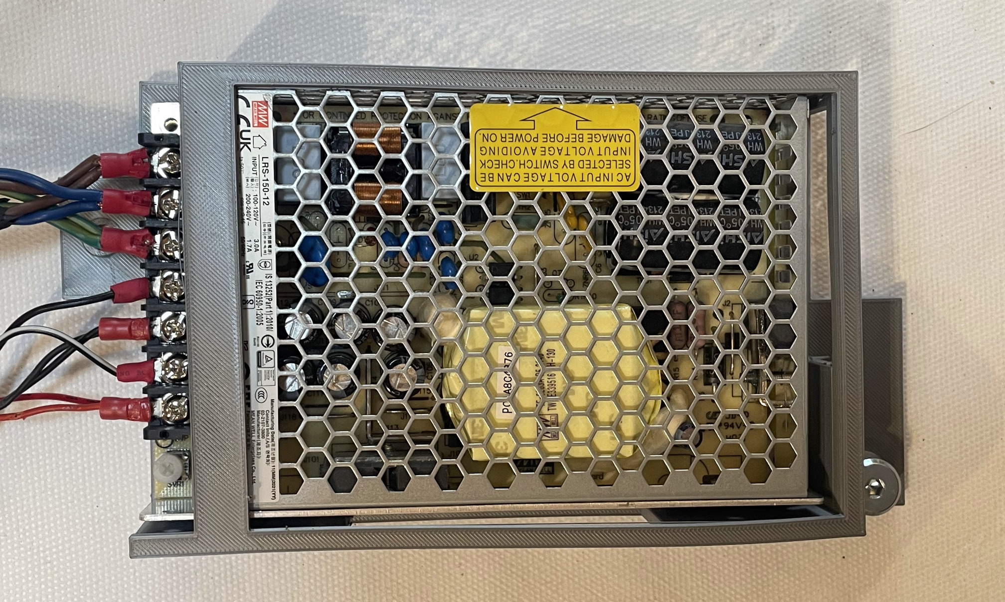
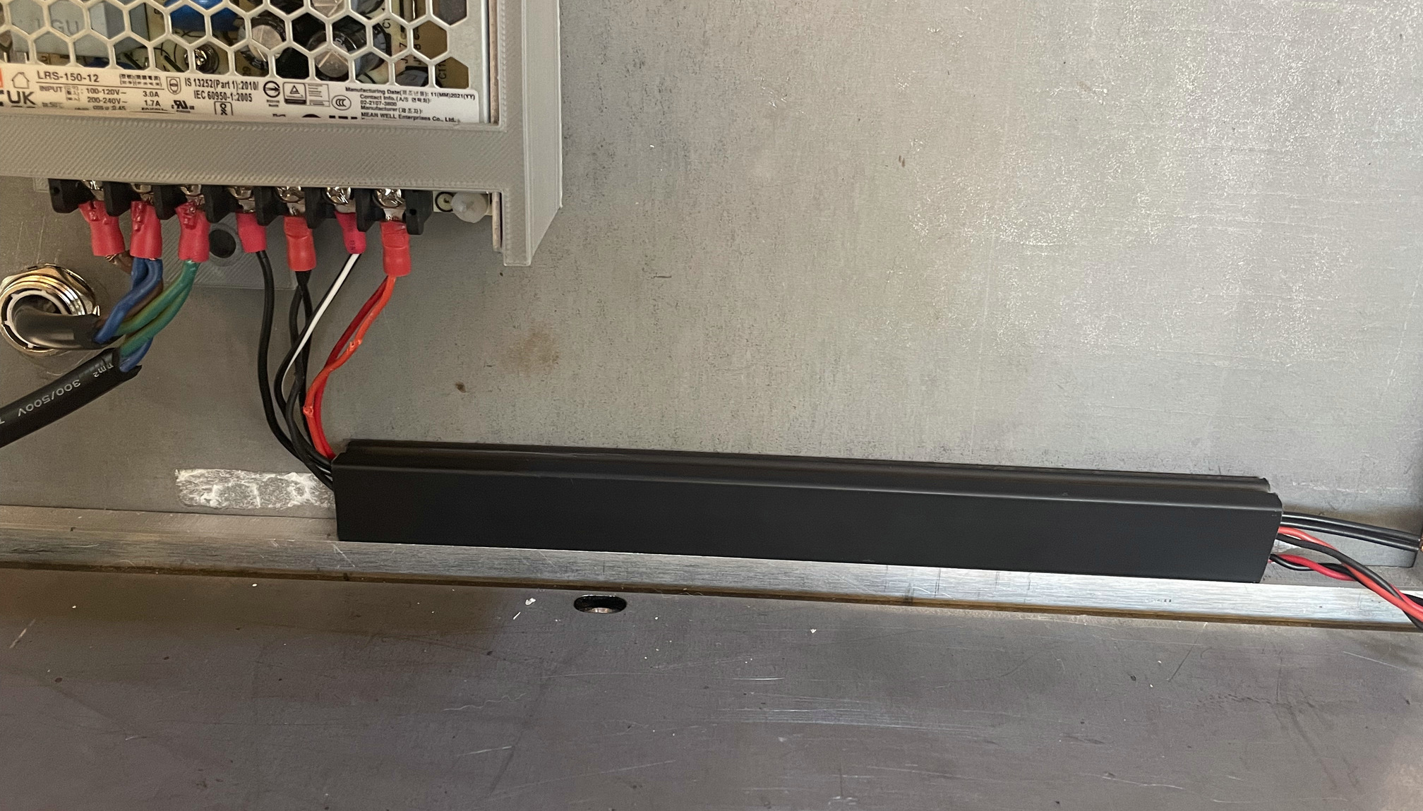
12V PSU
Wiring the screen
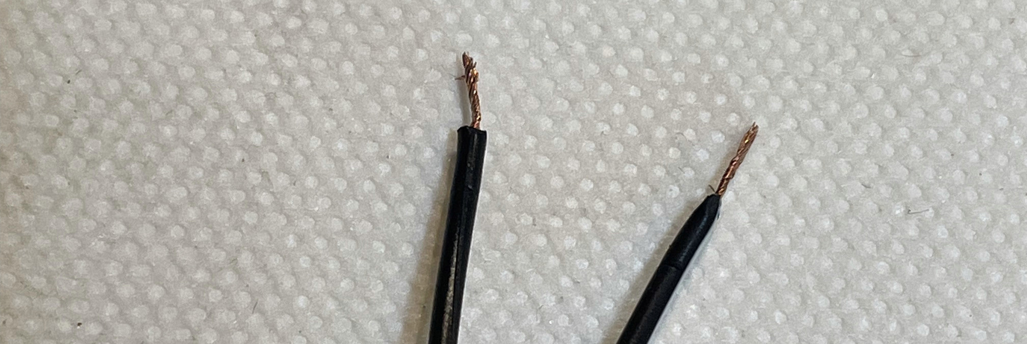
- Strip the bare end of C_SP if it is not done already.
- Pass each wire in 1x M_CF.
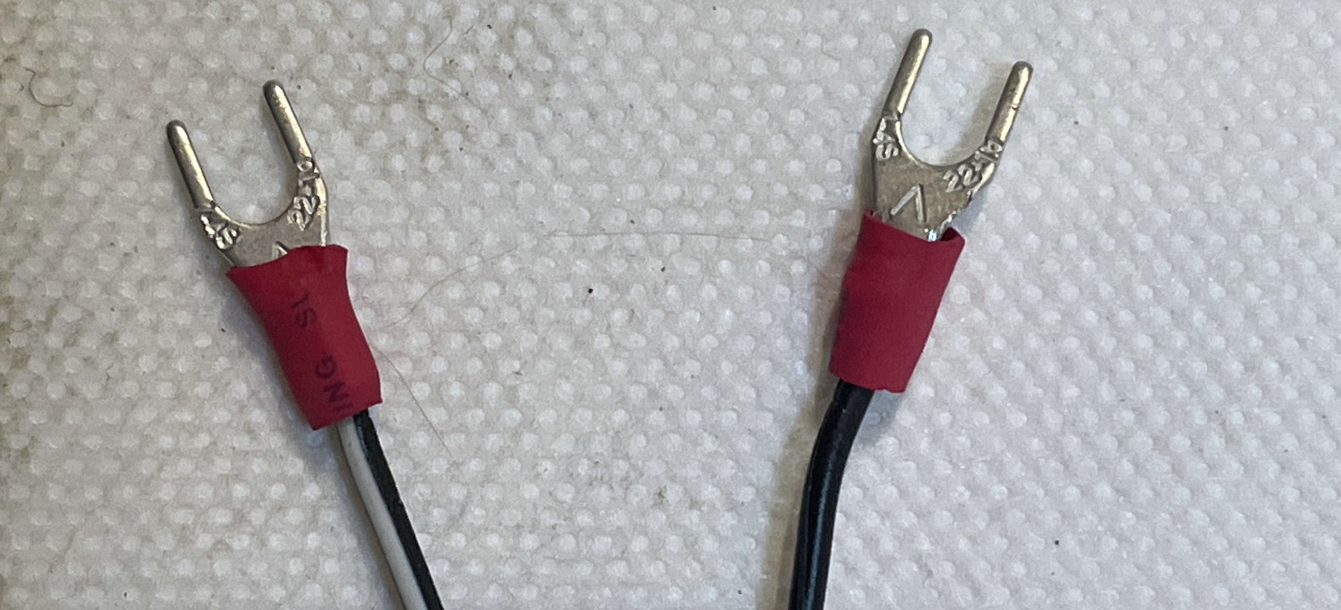
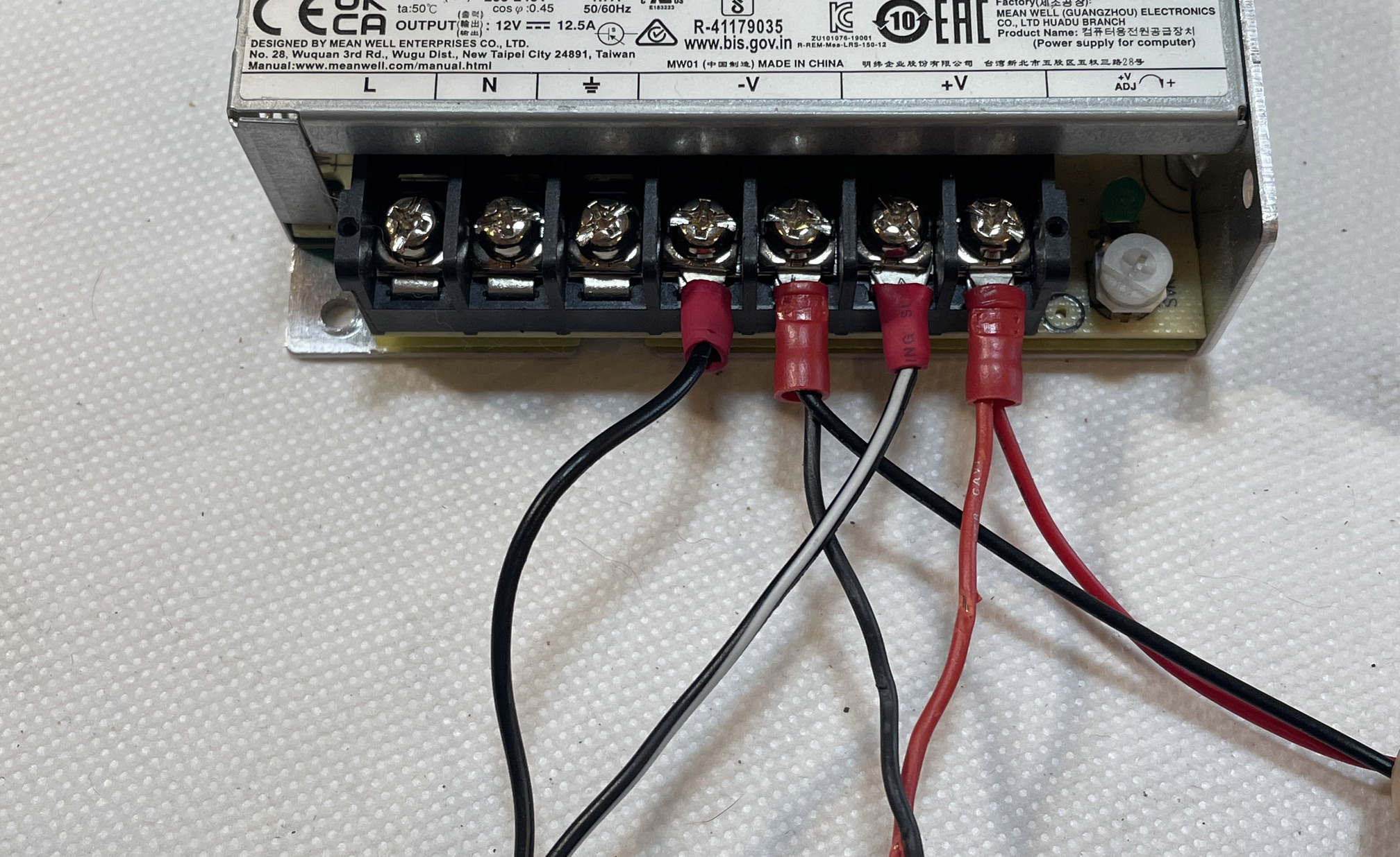
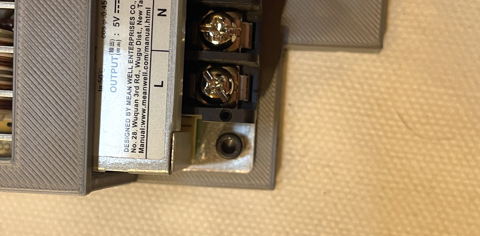
- On E_P12, unscrew the first
-Vand the first+Vfrom the left. Plug the black wire (with the cable connector) to-V(negative) and the black with a white line wire in+V(positive).
| L | N | ⏚ | -V | -V | +V | +V |
|---|---|---|---|---|---|---|
| plain black | White line / dash |
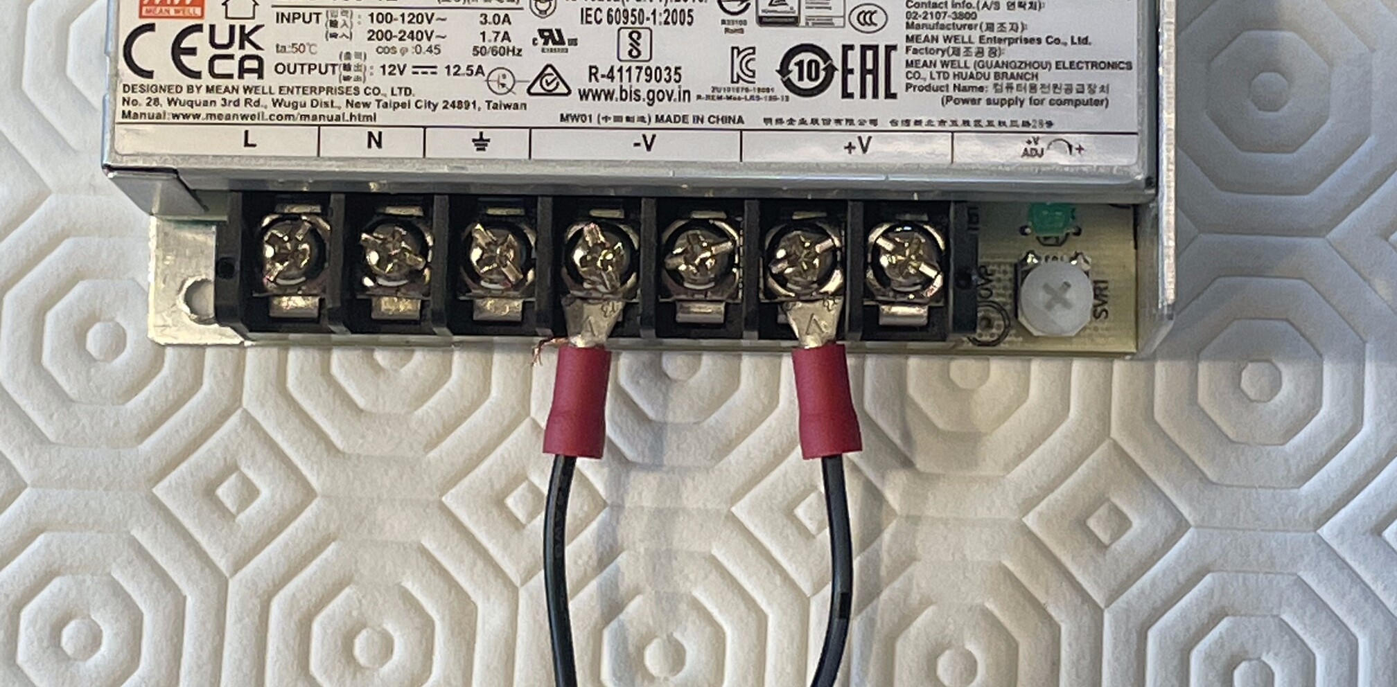
- On E_P12, screw the 2 screws back.
Wiring cash devices
- On C_OC, unplug C_O42 and C_O41 if it is not done already.
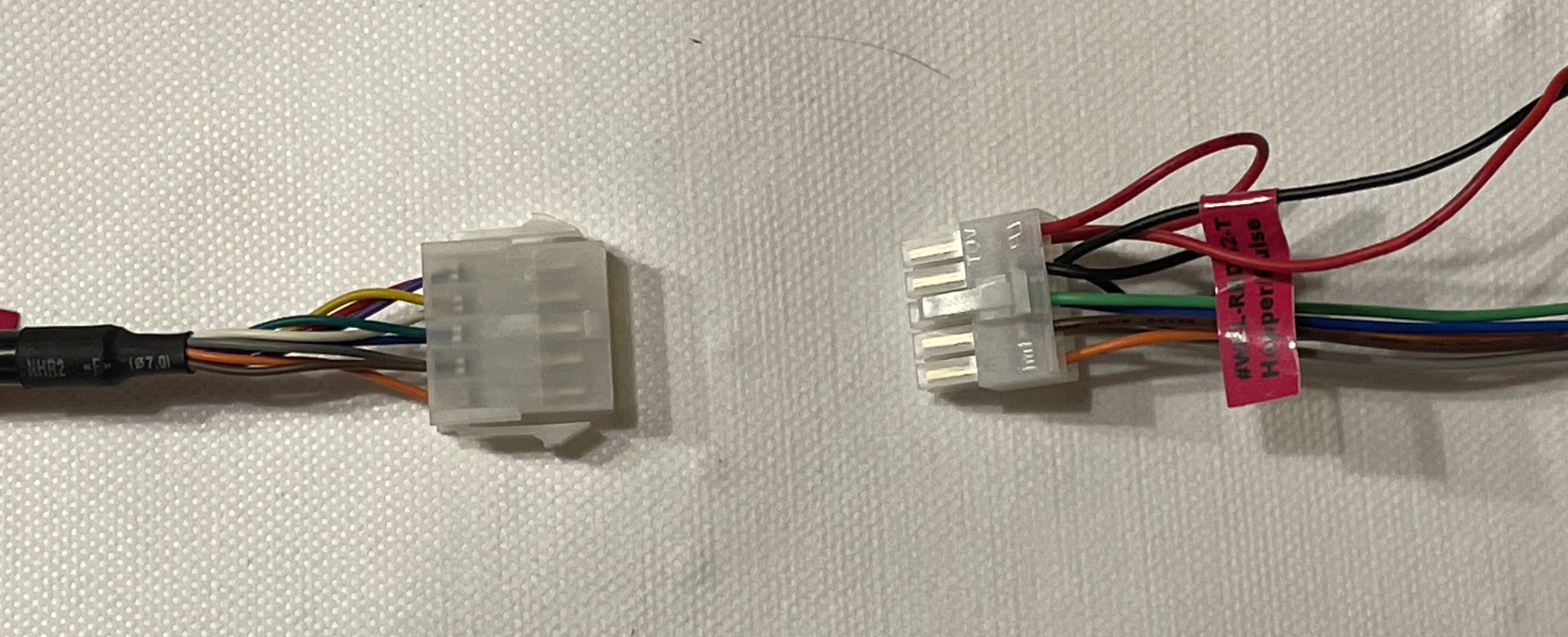
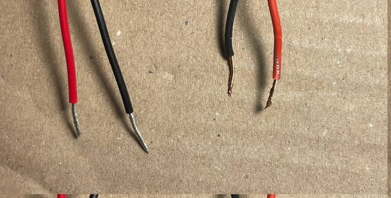
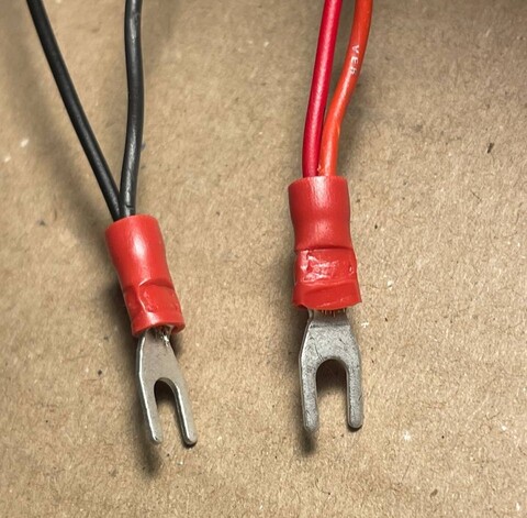
- On C_OP, remove the default fork cable connectors from the red and black wires.
- Pass the black power wires from C_IP and C_O42 through the same M_CF.
- Pass the red power wires from C_IP and C_OP through the same M_CF.
- Crush the cylindrical part of M_CF with the wires on the inside with a crimping tool. If you don't have a crimping tool, you can crush the fork connector using a simple plier. Do that for the red and the black wires.
- On E_P12, unscrew the second
-Vand the second+Vfrom the left. - Plug the black cables (with M_CF) in the
-Vslots. - Plug the red cables (with M_CF) in the
+Vslots.
| L | N | ⏚ | -V | -V | +V | +V |
|---|---|---|---|---|---|---|
| black | red |
- On E_P12, screw the 2 screws back.
Wiring main power cable and 5V relay
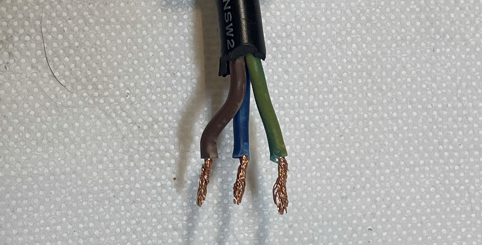
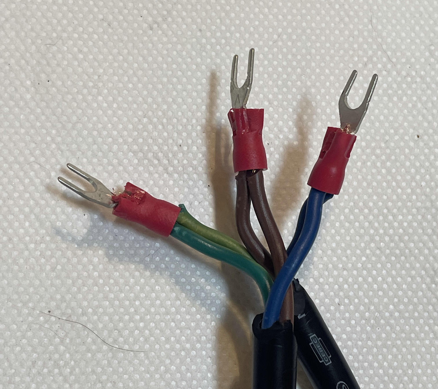
- Strip C_PC and C_PR on 7cm.
- Strip the 3 wires of C_PC on 0.5cm.
- Strip the 3 wires of C_PR on 0.5cm.
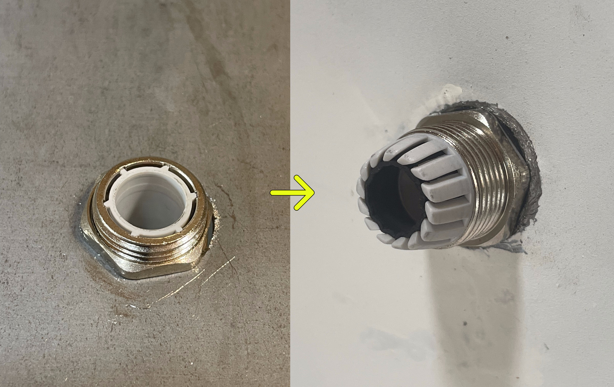
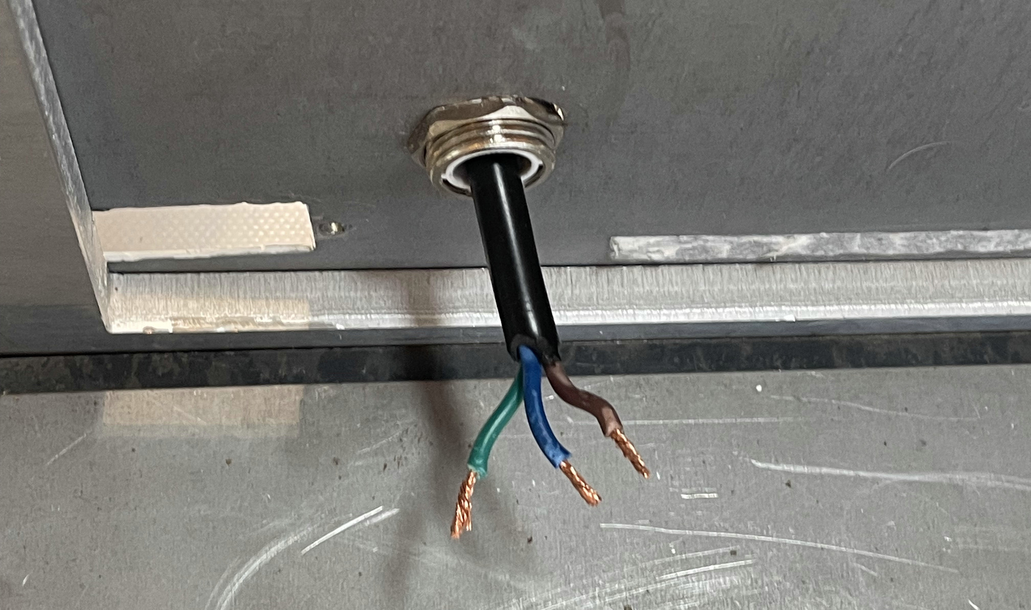
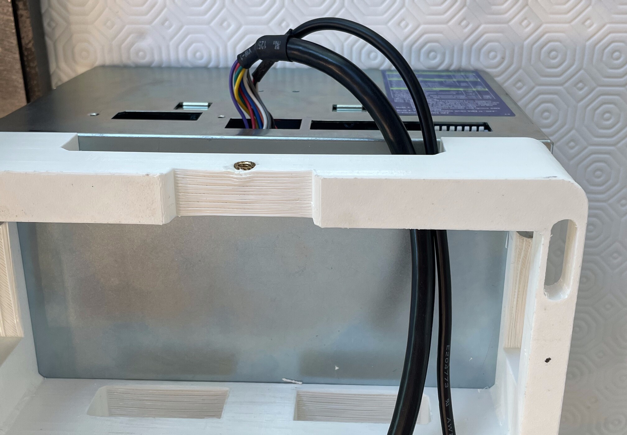
- On the Swapbox, unscrew M_CG compression nut.
- Pass C_PC through the compression nut of M_CG. Make sure that the screw side of the compression nut is facing the bare wires side of the cable.
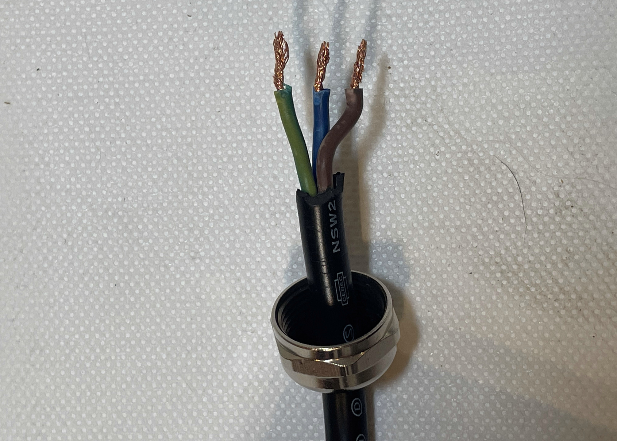
Pass C_PC through M_CG on the Swapbox.
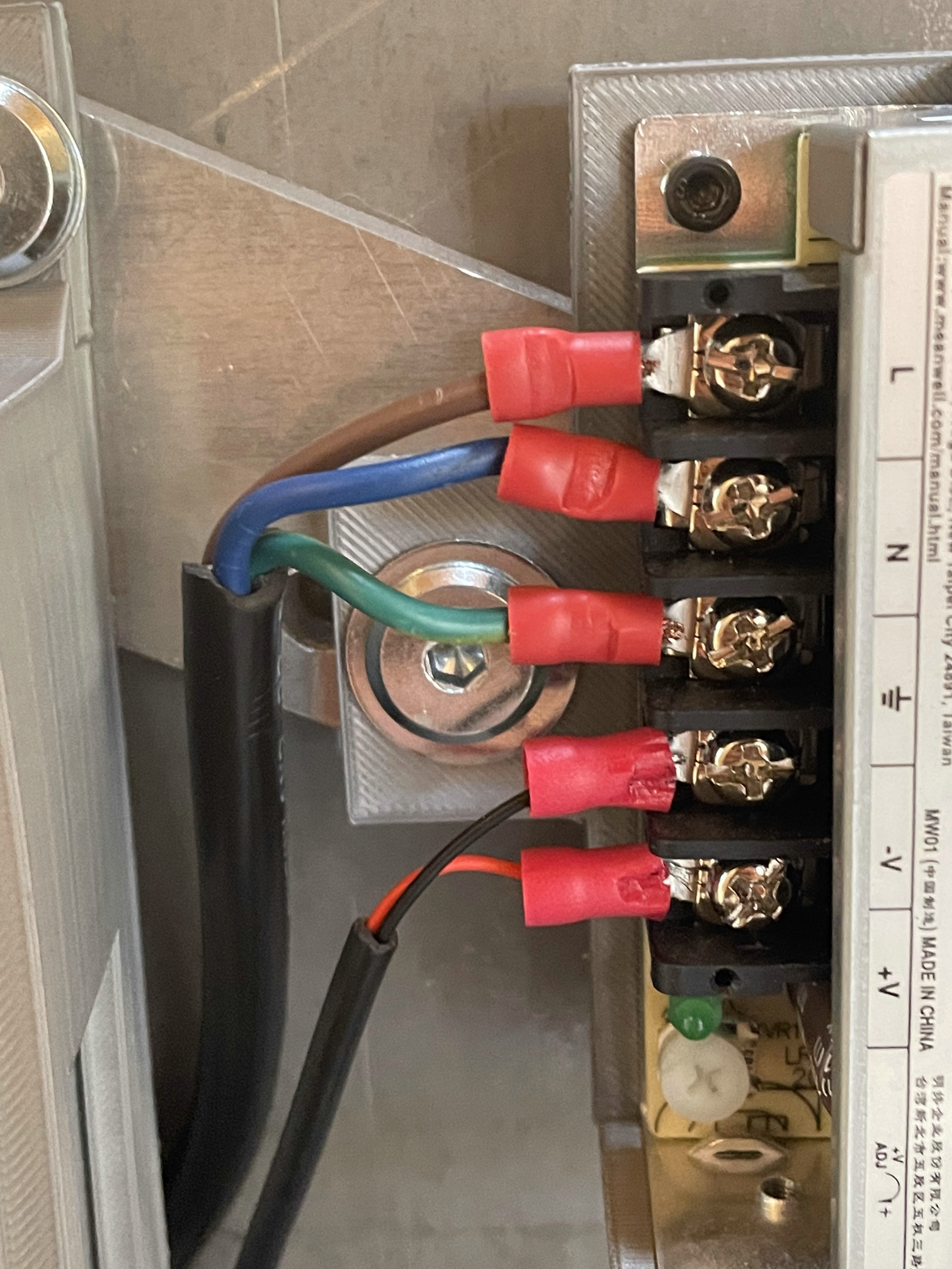
- Pass the 2 brown wires of C_PR and C_PC to the same M_CF.
- Pass the 2 blue wires of C_PR and C_PC to the same M_CF.
- Pass the 2 green wires of C_PR and C_PC to the same M_CF.
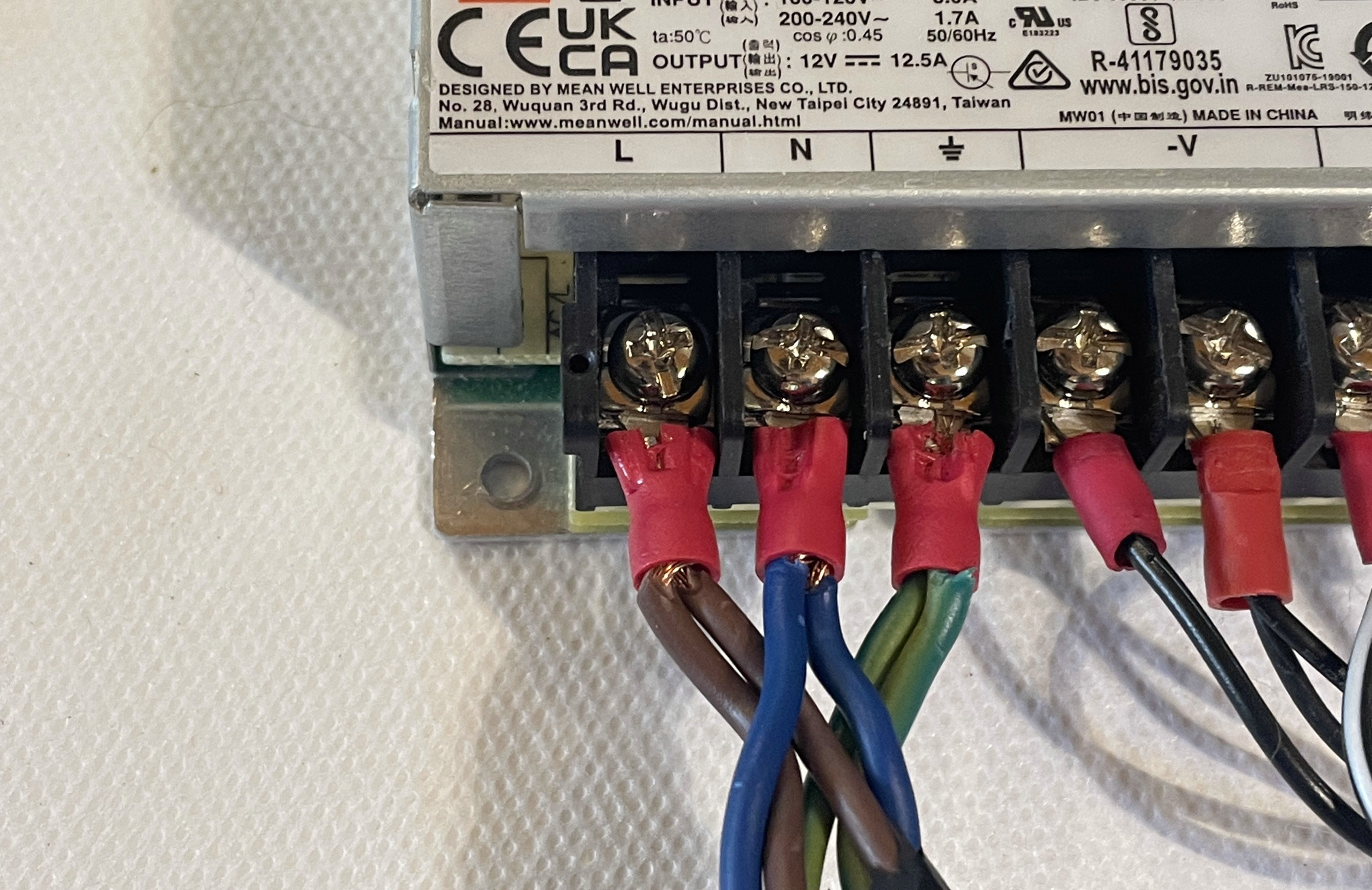
- On E_P12, unsrew the 3 first screws from the left (
L,N,⏚slots). - Plug the brown wires into the
Lslot. - Plug the blue wires into the
Nslot. - Plug the green wires into the
⏚slot.
| L | N | ⏚ | -V | -V | +V | +V |
|---|---|---|---|---|---|---|
| Brown | Blue | Green |
- On E_P12, screw the 3 screws back.
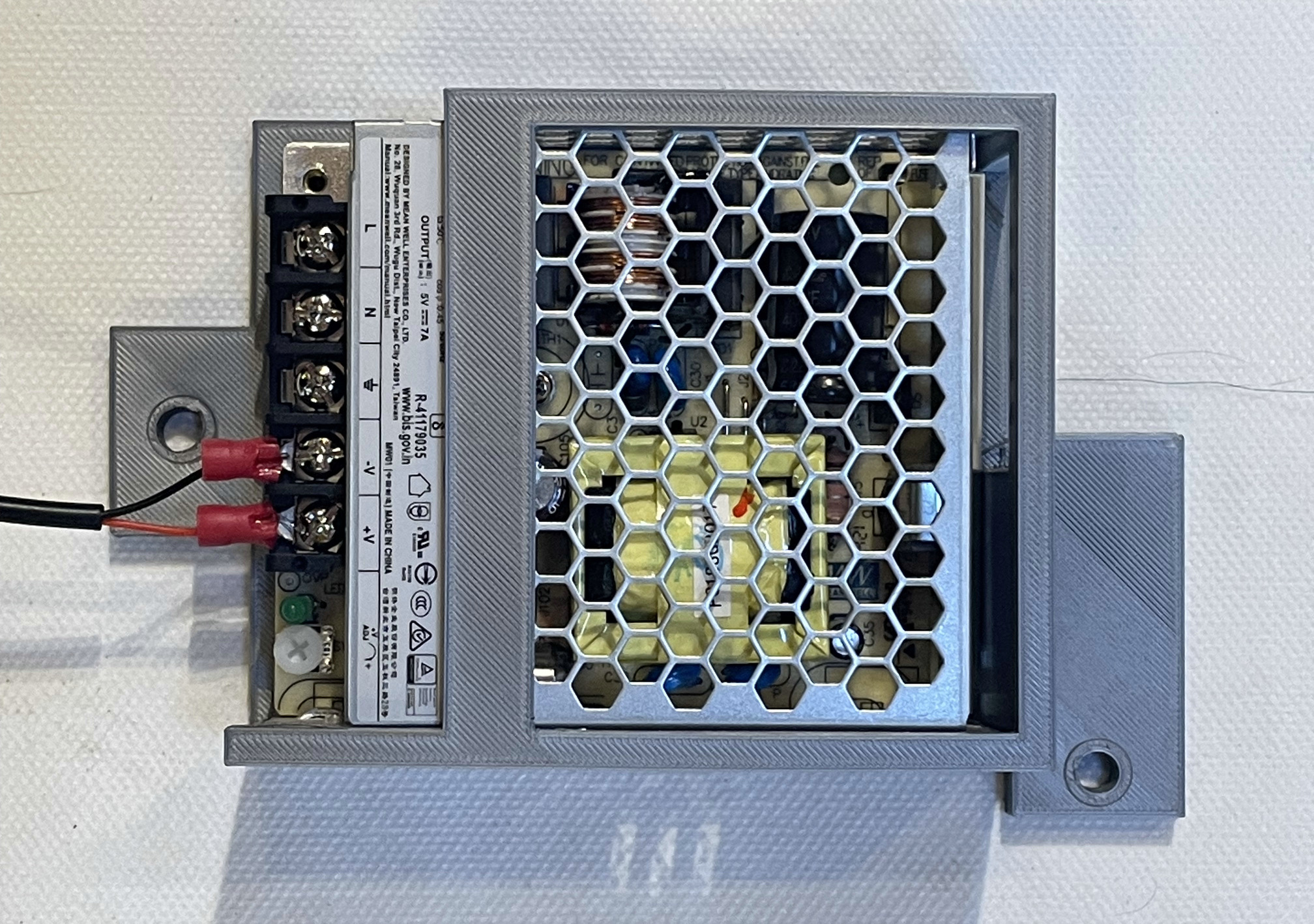
5V PSU
Wiring Rasperry Pi 4
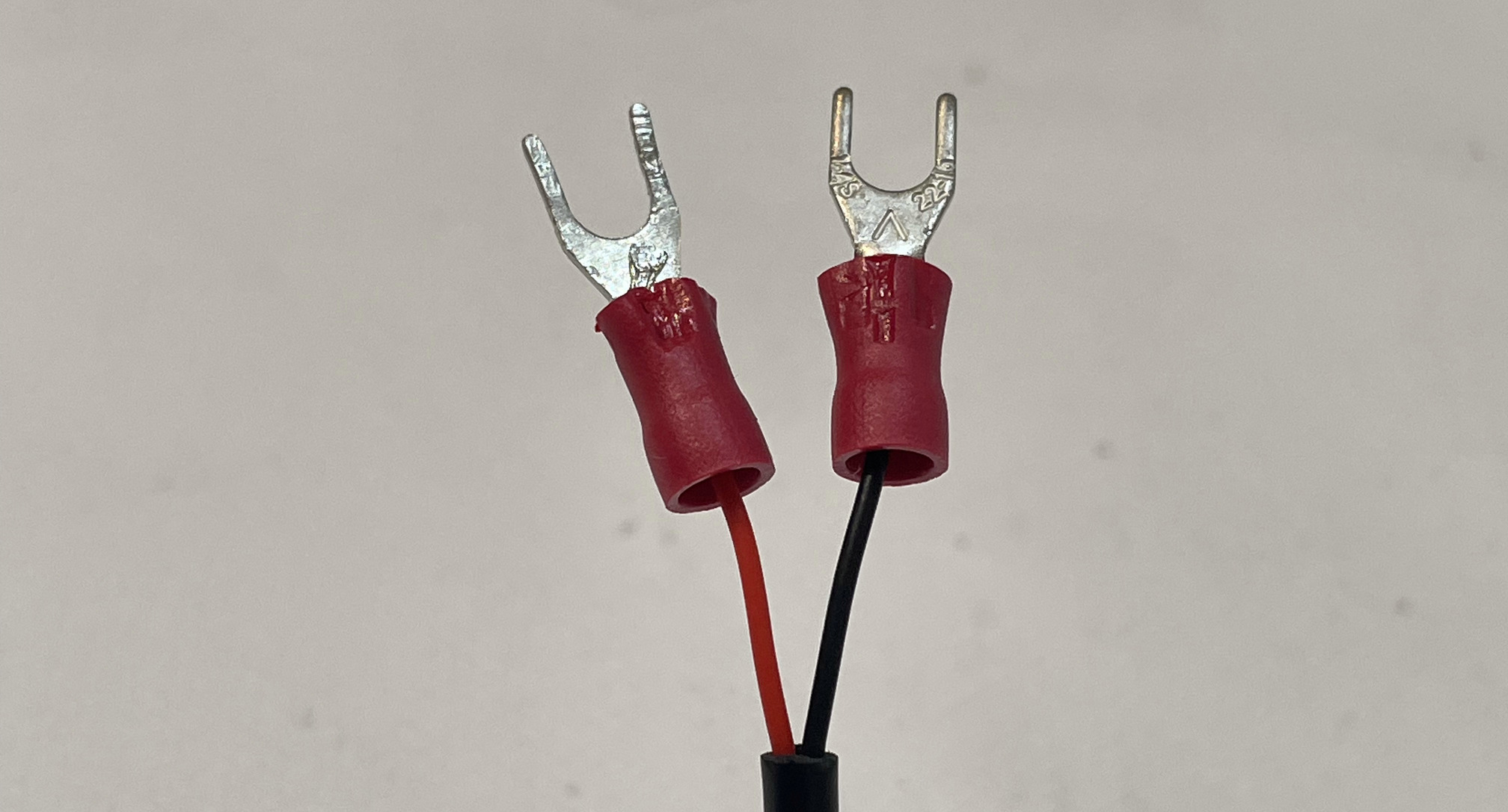
- Strip the black and red wires of C_RP if it is not done already. Insert each wire in 1x M_CF.
- On E_P12, unsrew the 2 screws on the far right (slot
-Vand+V) - Plug the black wire (with the M_CF) in the
-Vslots and the red wire (with M_CF) the+Vslots.
| L | N | ⏚ | -V | +V |
|---|---|---|---|---|
| black | red |
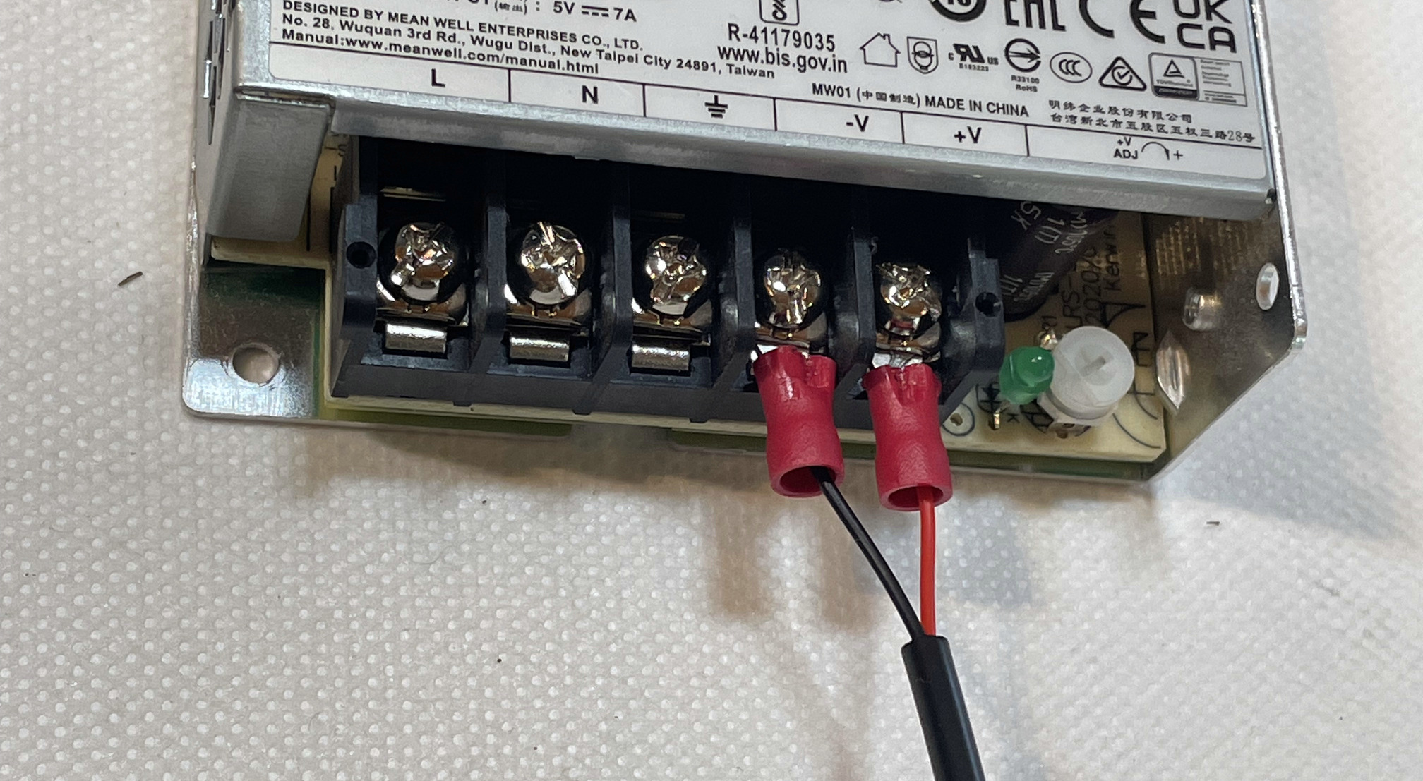
- On E_P05, screw the 2 screws back.
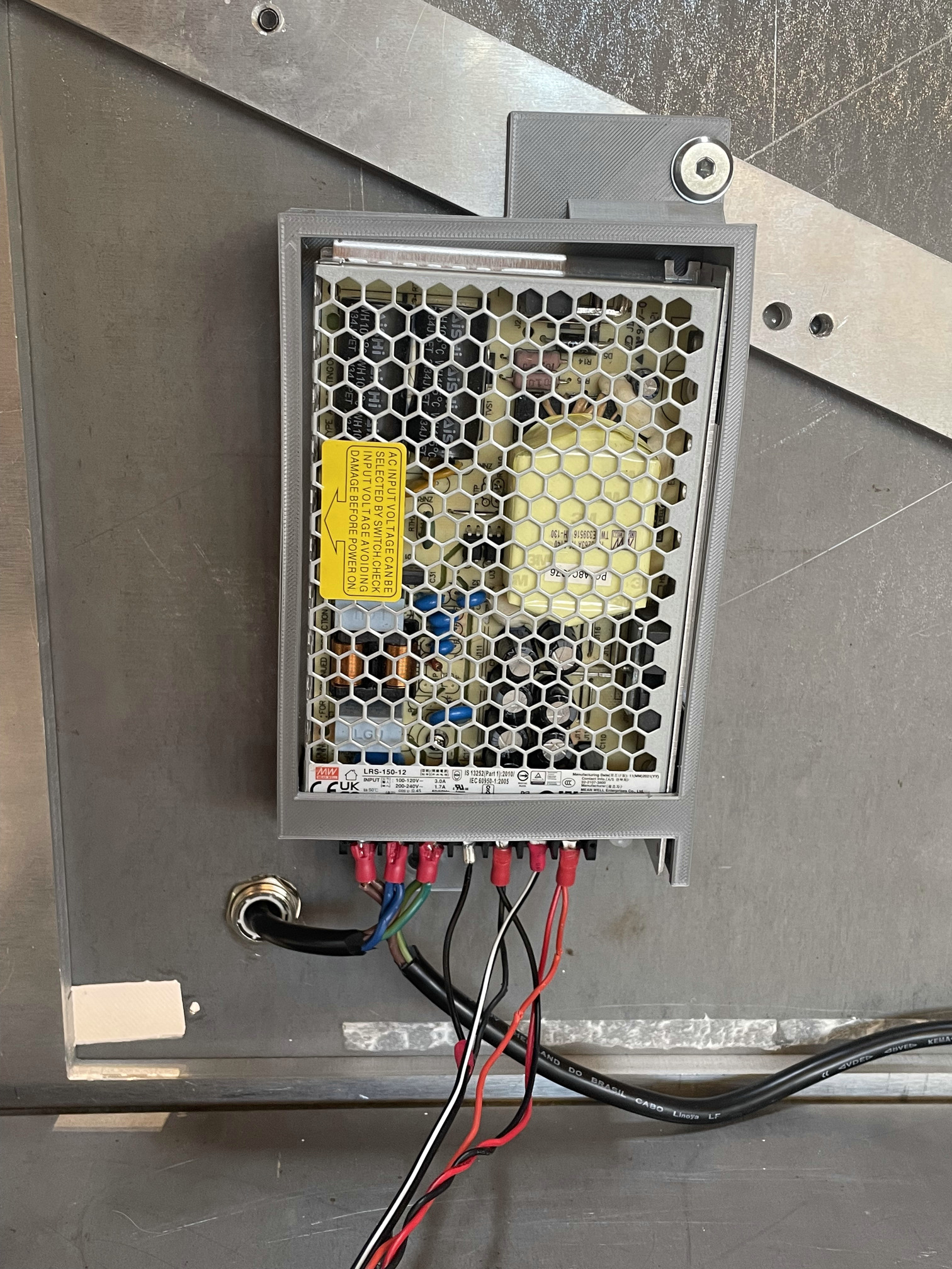
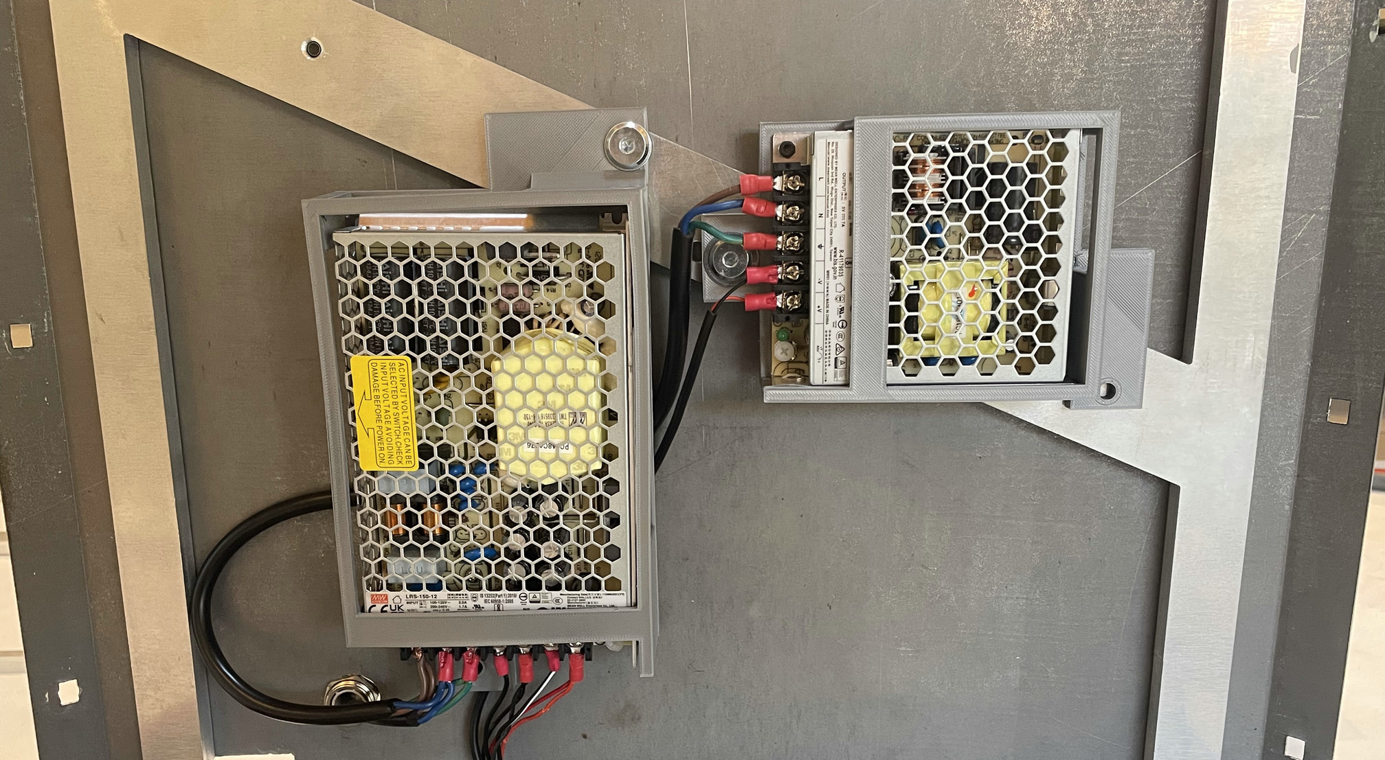
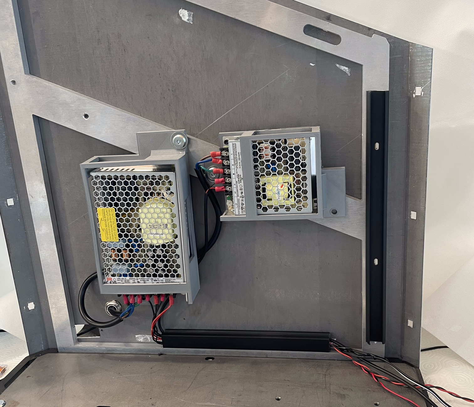
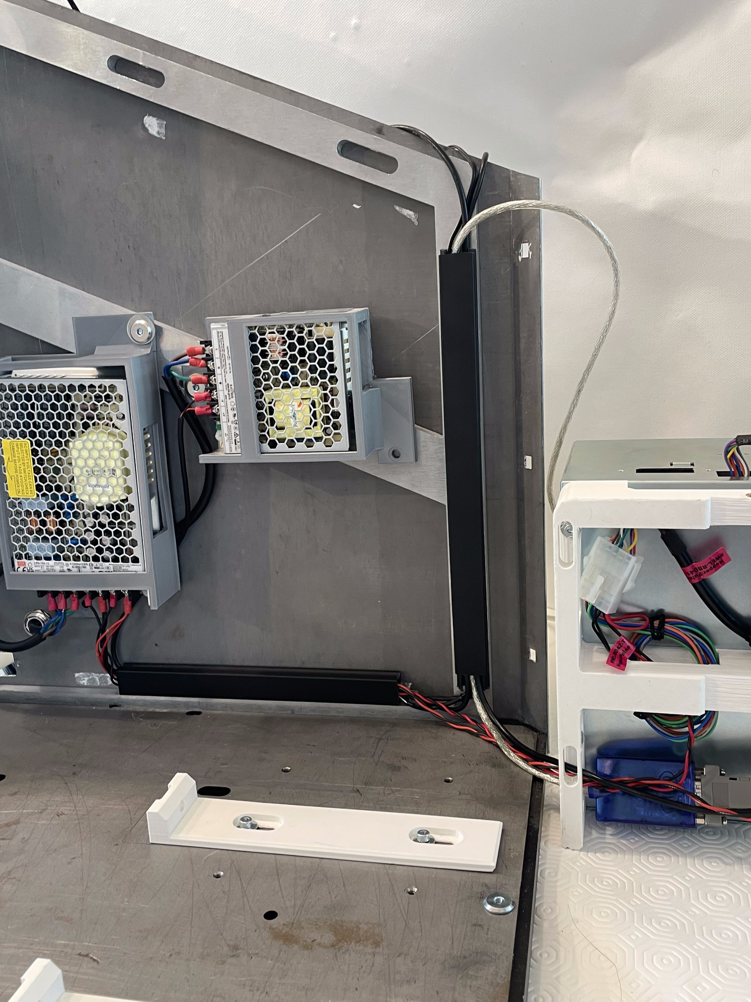
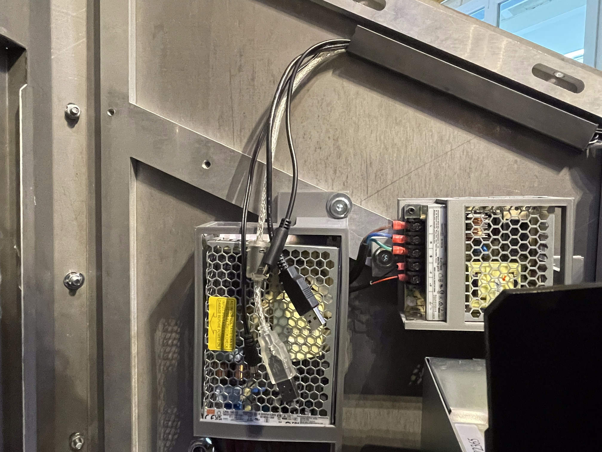
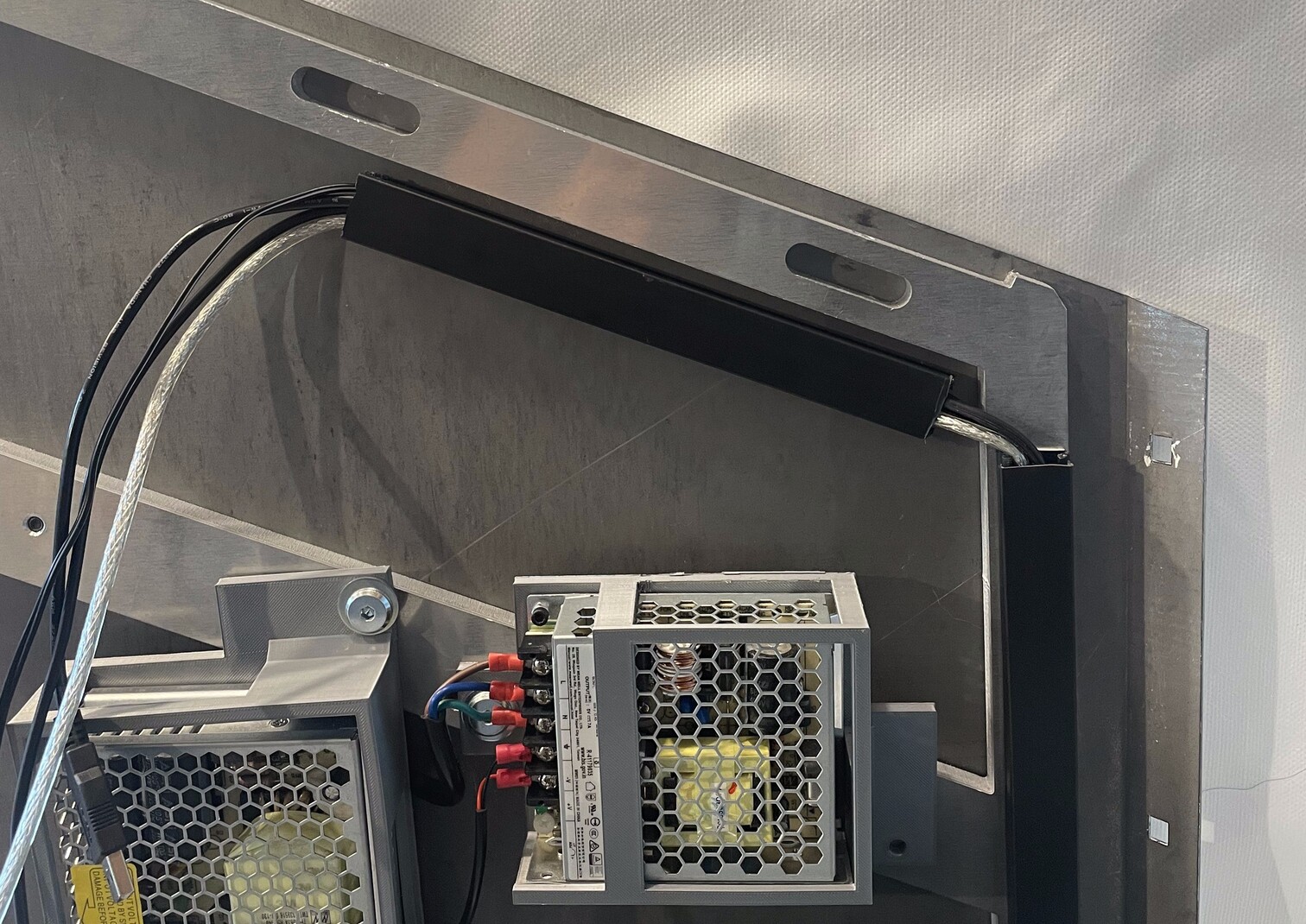
Mount PSUs
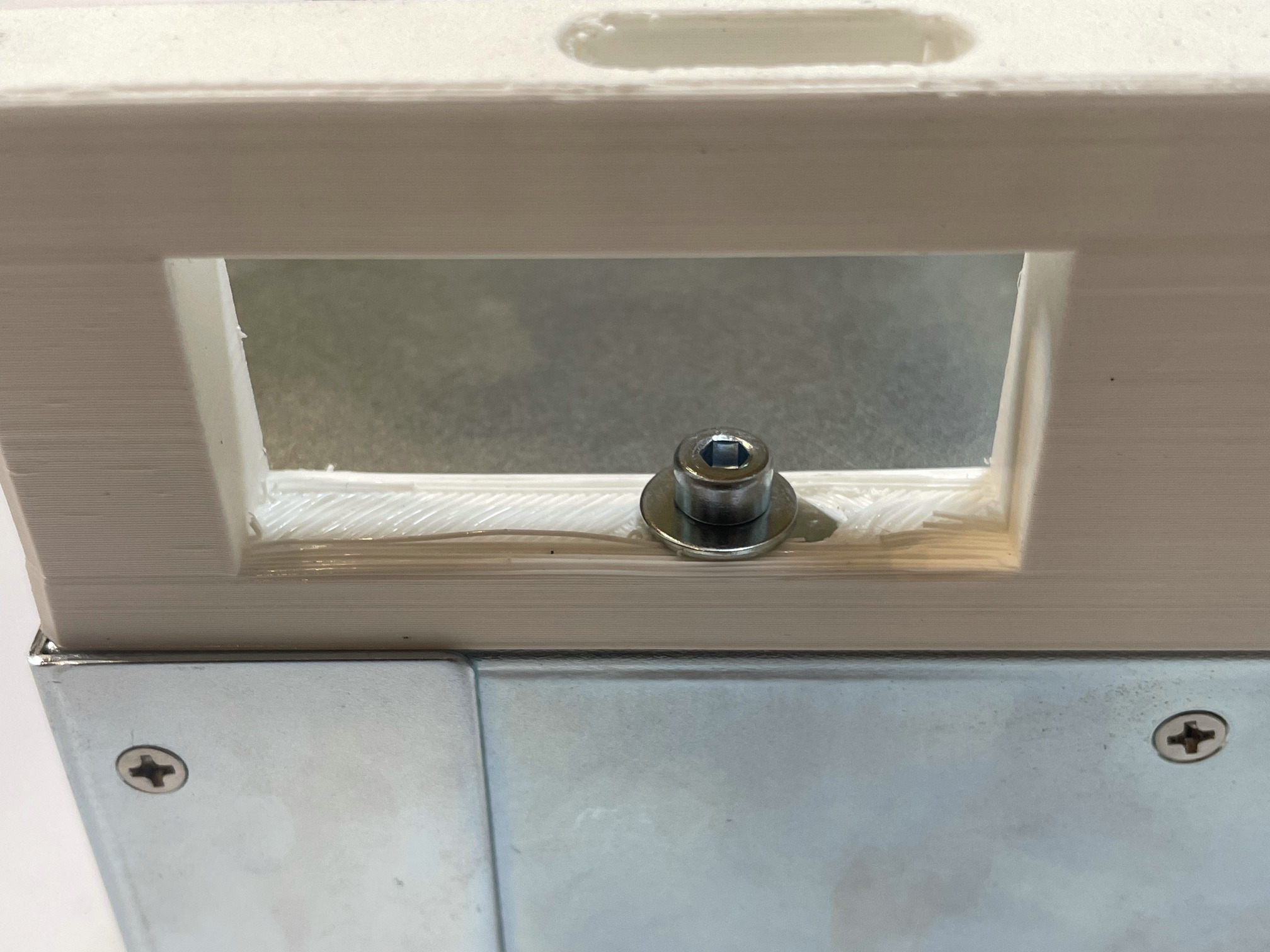
- Insert E_P12 in P_P12C. The screw-hole next to the connectors on E_P12 must be aligned with the small screw-hole on P_P12C.
- Attach E_P12 to P_P12C with 1x B_SS_M2_6
- Mount P_P12C on H_RS with 2x B_SS_M6_20 and 2x B_W_M8. E_P12 connectors must face downwards.
Carefully pass C_PR under P_P12C. Do not stress C_PR connectors.
Insert E_P05 in P_P05C. The screw-hole next to the connectors on E_P05 must be aligned with the small screw-hole on P_P05C.
- Attach E_P05 to P_P05C with 1x B_SS_M2_6
- Mount E_P05 on H_RS with 2x B_SS_M6_20 and 2x B_W_M8. E_P05 connectors must be facing to P_P12C.
- Pass C_RP (connected to E_P05) under P_P12C, to make the cable less visible.
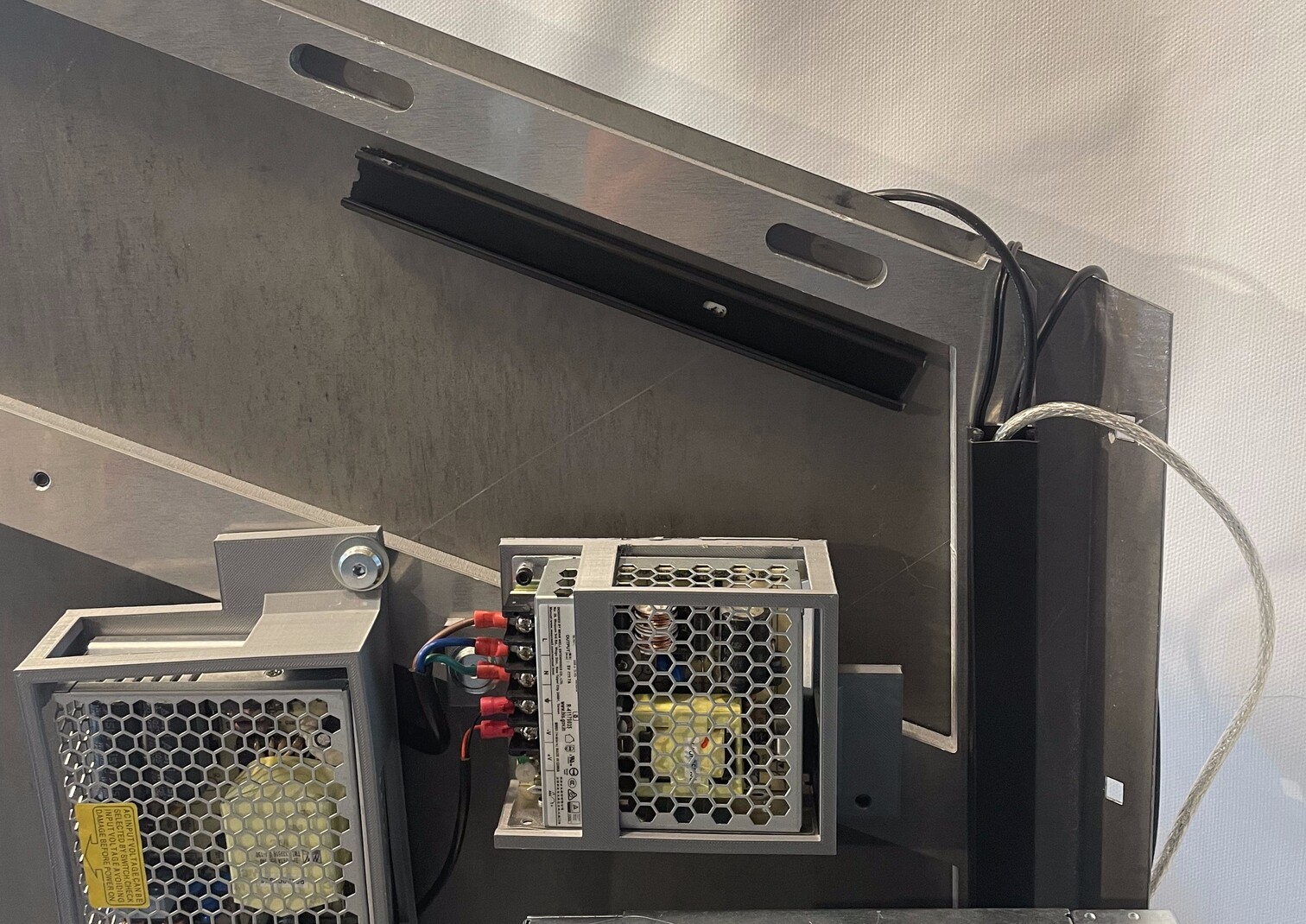
Connecting PSUs
- On he E_P05, unscrew the 3 screws
L,Nand⏚. - Plug the brown wire into the
Lslot on E_P05. - Plug the blue wire into the
Nslot on E_P05. - Connect the green wire to the
⏚slot on E_P05.
- On E_P05, screw the 3 screws back.
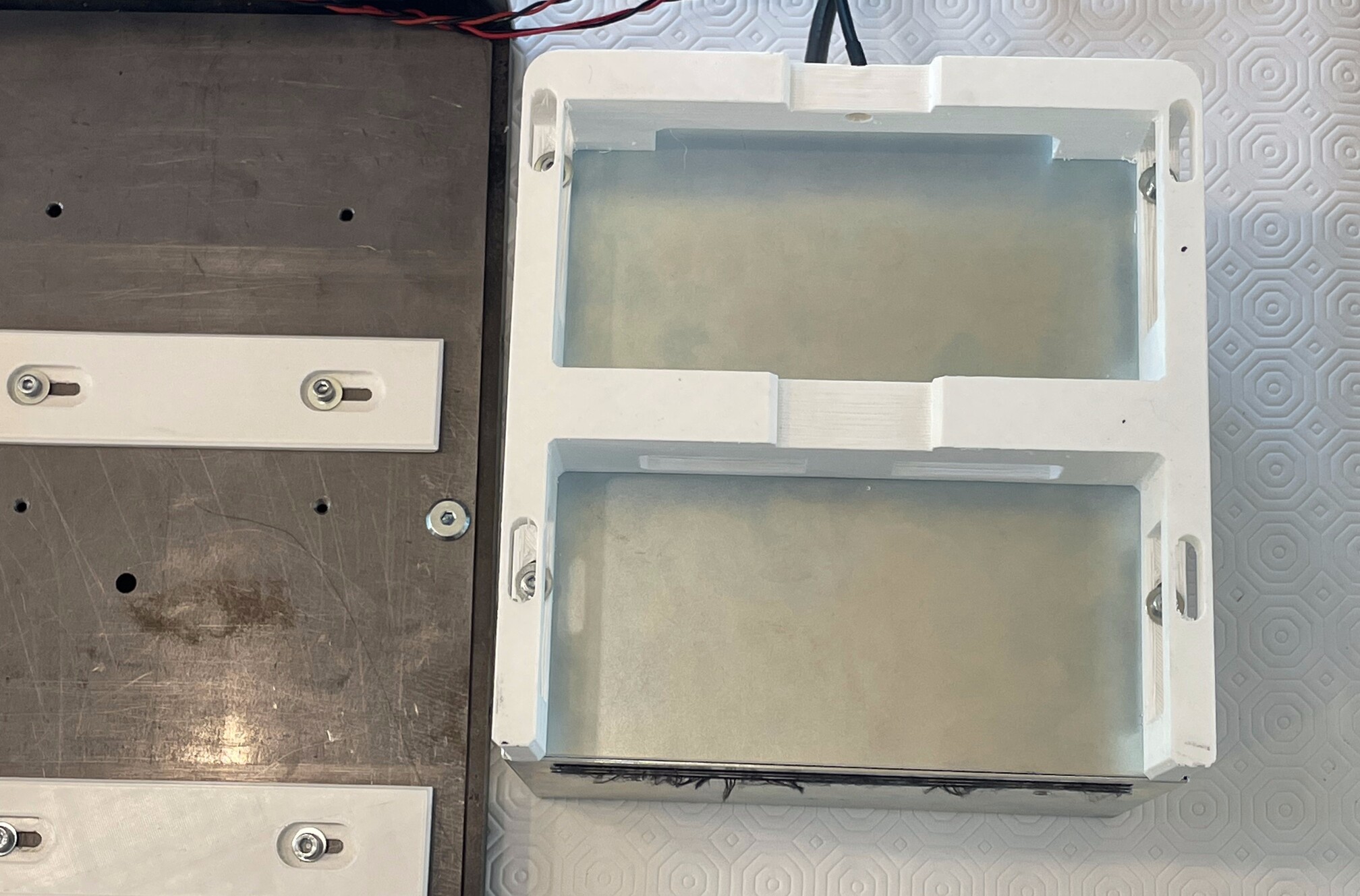
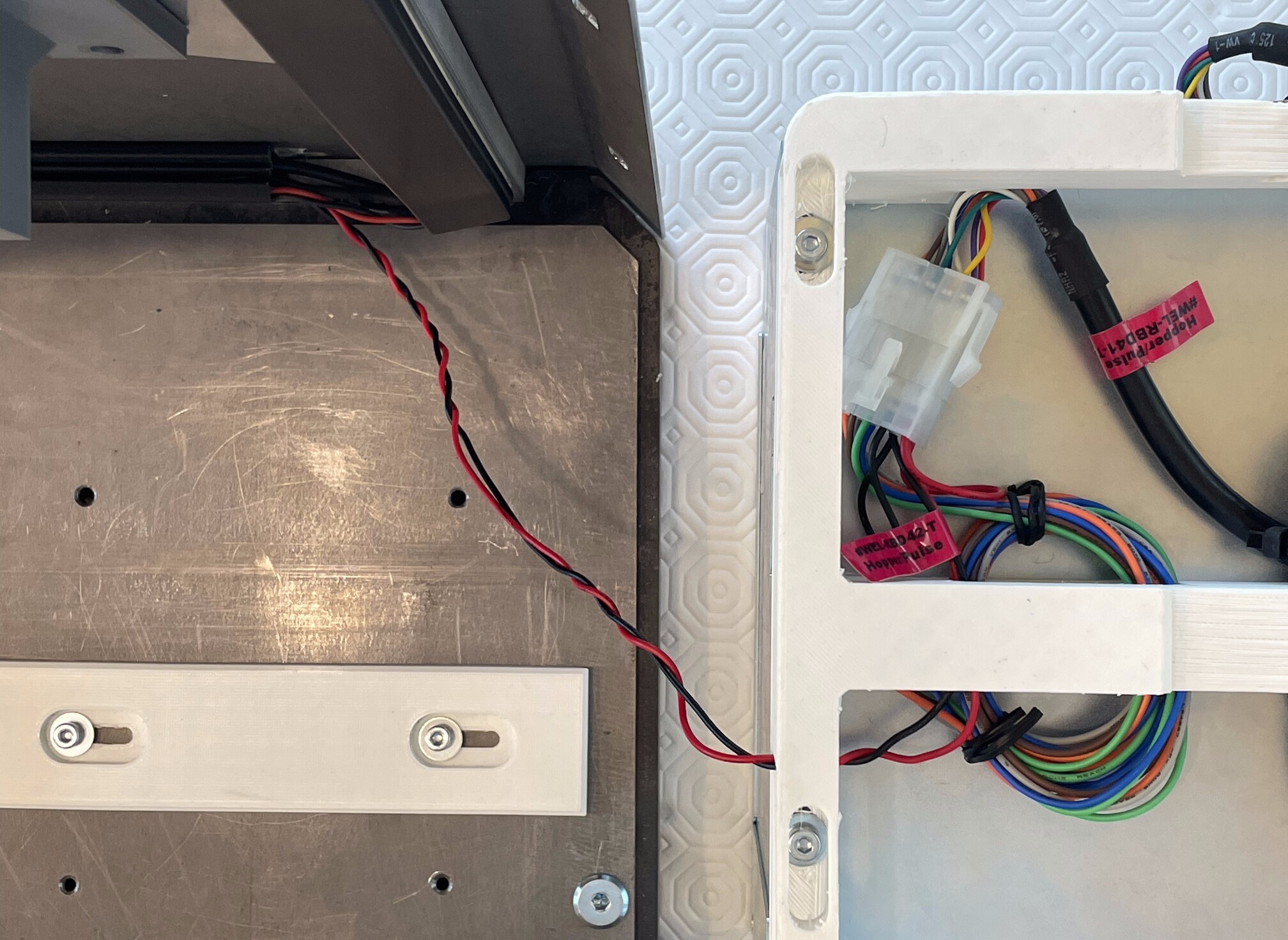
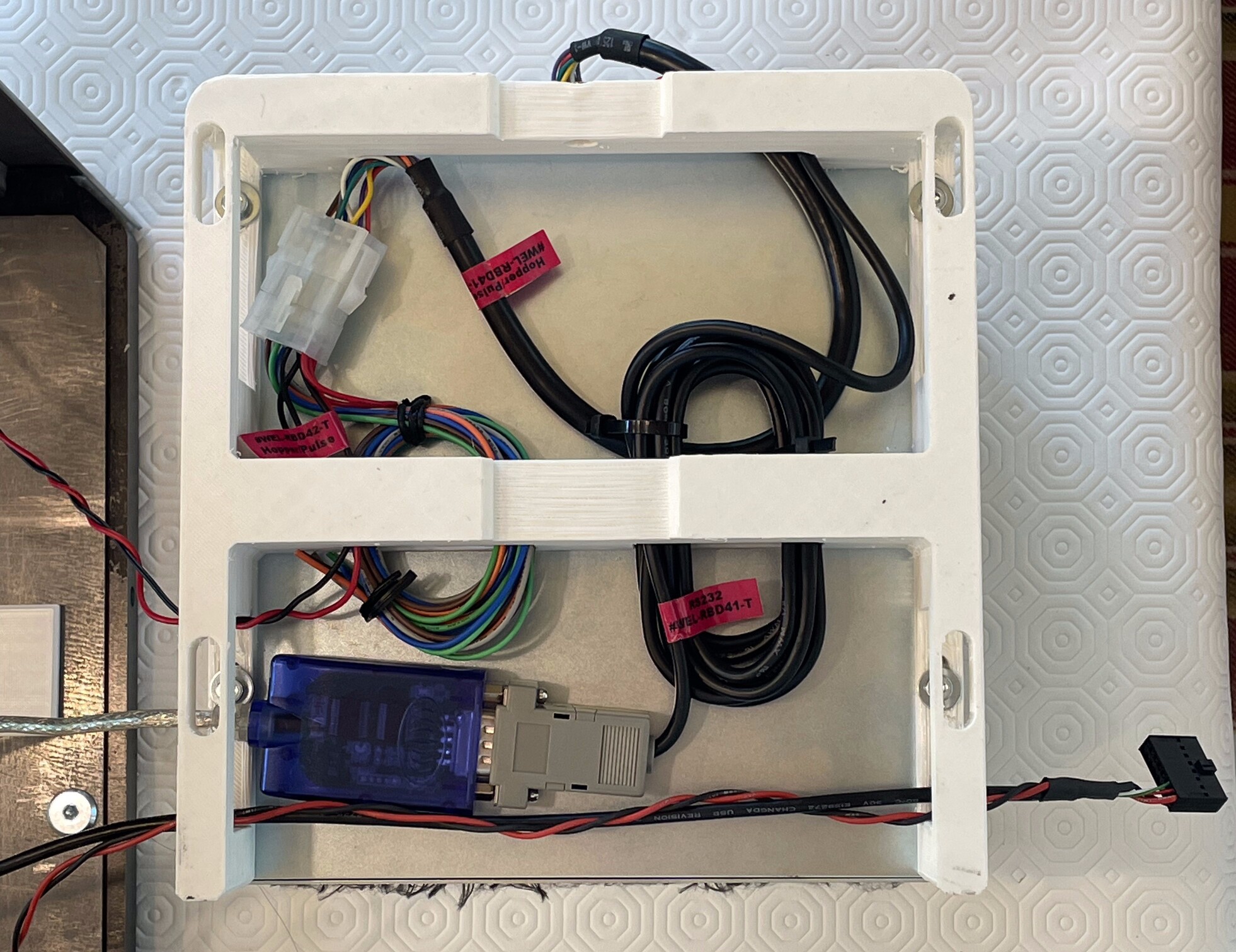
- Stick M_T_RPB at the bottom of H_RP, parralelly to the bottom of H_RS. It should not be in contact with H_RS.
- Pass C_SP, C_O42, C_IP and C_RP through M_T_RPB. Do not stretch the wires, but avoid leaving them too loose.
- Slide the upper part of M_T_RPB out.
- Clip the M_T_RPB lid to the M_T_RPB base.
Cable management
| Qty | Part ID | Part description |
|---|---|---|
| 1 | Swapbox | |
| 1 | Cashout component | |
| 4 | M_ZT | |
| 1 | C_ID | |
| 1 | C_O41 | |
| 1 | C_OA | |
| 1 | M_T_RSR | |
| 1 | M_T_RPT | |
| 1 | M_T_LSL |
- Slide the upper part of M_T_RSR out.
- Stick M_T_RSR on the right side of H_RS, vertically.
Pass C_SP and C_RP through M_T_RSR. Do not close M_T_RSR yet: we will have to pass more cable through it.
- On C_O42, cut the visible part of each unused bare wires (blue, orange, grey, brown, green).
- On C_O42, make a small, clean loop with those 5 unused wires. Attach the loop with 2x M_ZT.
Hiding cables in cash-out component
P_OM diagram
- Place Cashout component right beside the front of the Swapbox. Make sure to place it like the figure below.
- Plug C_OC in the TMT 2*6 slot on E_COU. and pass the 2 cables through
Tfromoutside. Do not stretch the cable, but avoid leaving them too loose.
Pass the loop you made with C_O42 wires through the LB gap on P_OM from Outside.
Insert the loop in the
MLfromoutsidegap on P_OM.Connect C_O41 to C_O42 by plugging in the male and female MOLEX connectors.
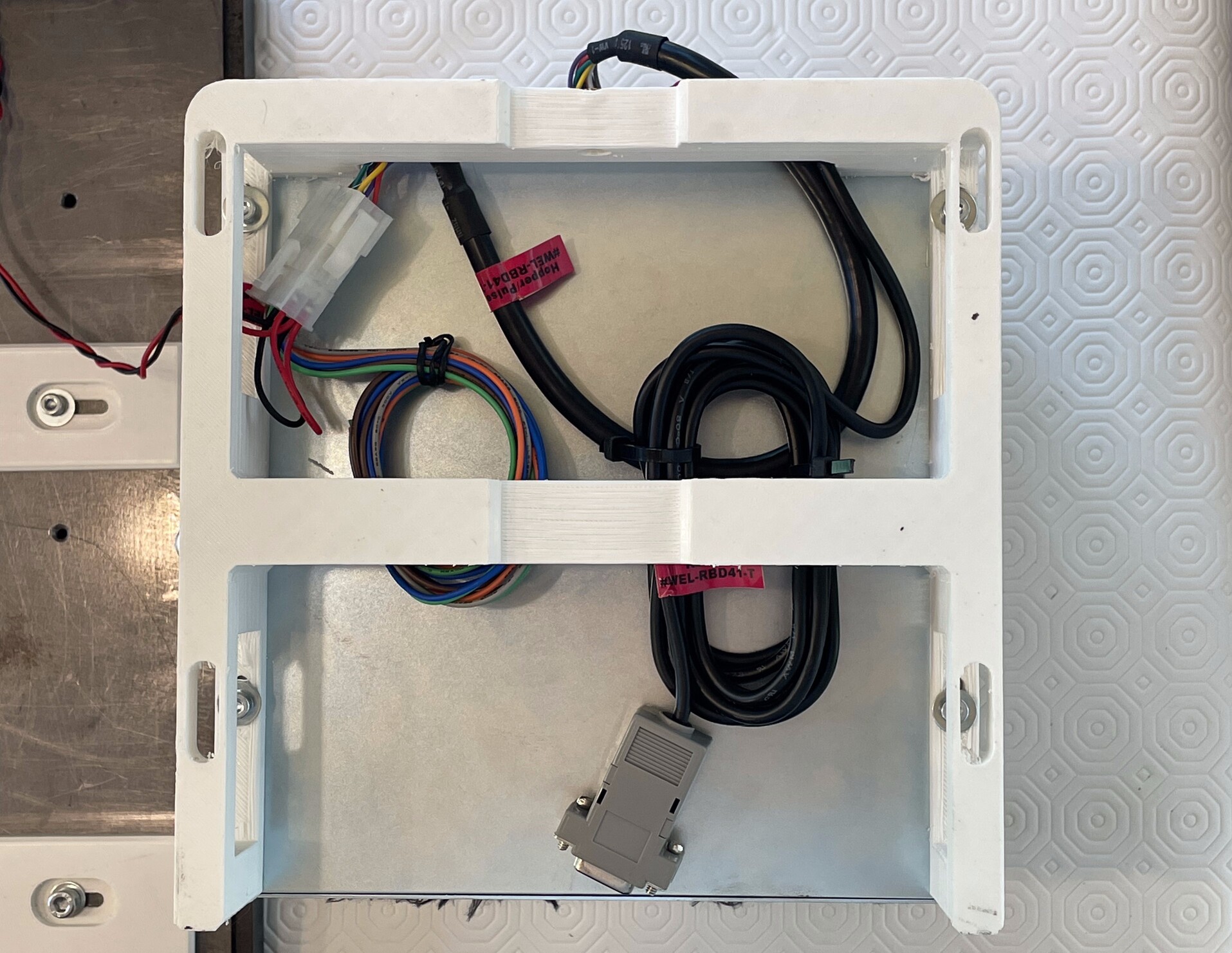
- Make a loop with the RS232-ended cable from C_O41. Attach the loop with 2x M_ZT.
- Trap the loop in the MR gap. The RS232 connector must come out from the inside (bottom).
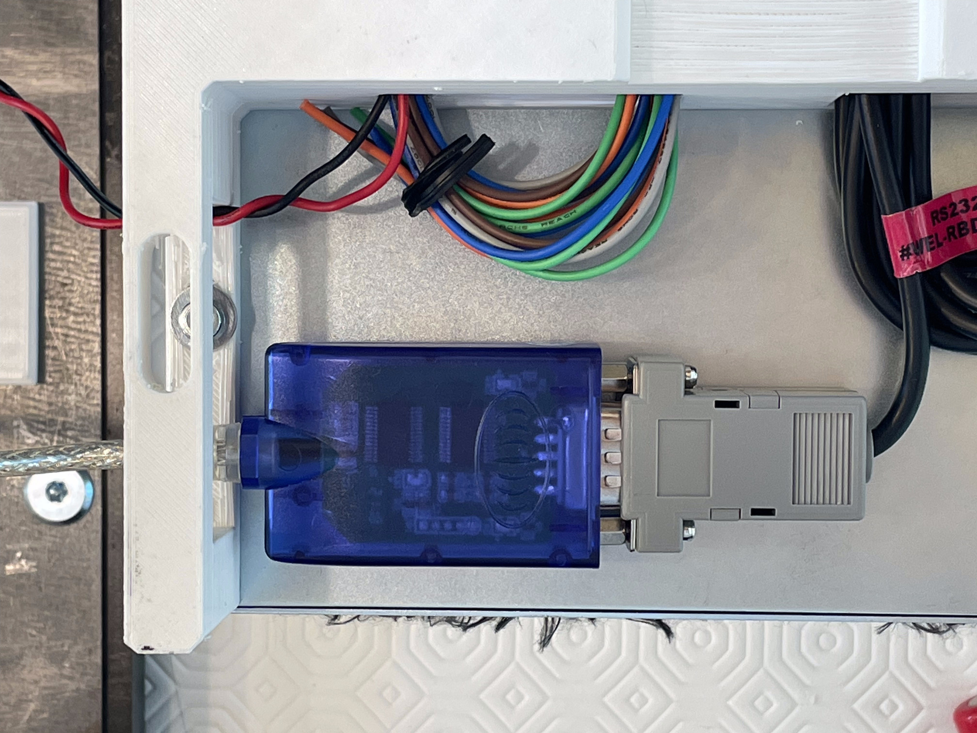
- Plug the RS232-ended cable from C_O41 to C_OA.
- Pass C_OA USB connector through
LBfrominside.
- Pass C_IC (C_IP and C_ID) through
LBfromoutsideandRBfrominsiderespectively.
Routing cables through trunking
- Pass the USB-A cable from C_ID and C_OA through M_T_RSR.
- Clip the upper part of M_T_RSR in.
- While making sure that all the cables stay in place, position the Cashout component on top of P_BR1. Make sure there is no cable pinched between the device and P_BR1.
Slide the upper part of M_T_RPT out.
Tape M_T_RPT at the top of H_RP, underneath and parralel to the top of H_RS. It should not be in contact with H_RS.
- Pass C_RP, C_SP, C_ID, C_OD through M_T_RPT. At the end side of M_T_RPT, the remaining cables should be about 20cm long.
- Clip the upper part of M_T_RPT in.
Cables coming out from M_T_RPT should be about 20cm long. If they are longer, pull the excess cable from the bottom of M_T_RSR and hide them in the Cashout component.
Mount front to Swapbox
| Qty | Part ID | Part description |
|---|---|---|
| 1 | Swapbox | |
| 1 | Front component | Front panel with cashin component |
| 5 | B_CB_M6_10 | |
| 5 | B_W_M6 | |
| 5 | B_N_M6 | |
| 1 | M_T_FPR |
- Move Swapbox so that the front of the swapbox protrudes in order to access the underside of the front of the swapbox.
- Attach Front component to H_BS using 2x B_CB_M6_10, 2x B_W_M6 and 2x B_N_M6. Make sure no cables are pinched.
- Attach Front component to H_RP using 3x B_CB_M6_10, 3x B_W_M6 and 3x B_N_M6. Front component must be on the inside of H_RP.
- Slide the upper part of M_T_FPR out.
- Tape M_T_FPR vertically on the right of H_FP.
- Pass C_IC through M_T_FPR.
- Clip the upper part of M_T_FPR back in.
- Plug C_IC into the IDC 16-pin connector on E_CIN.
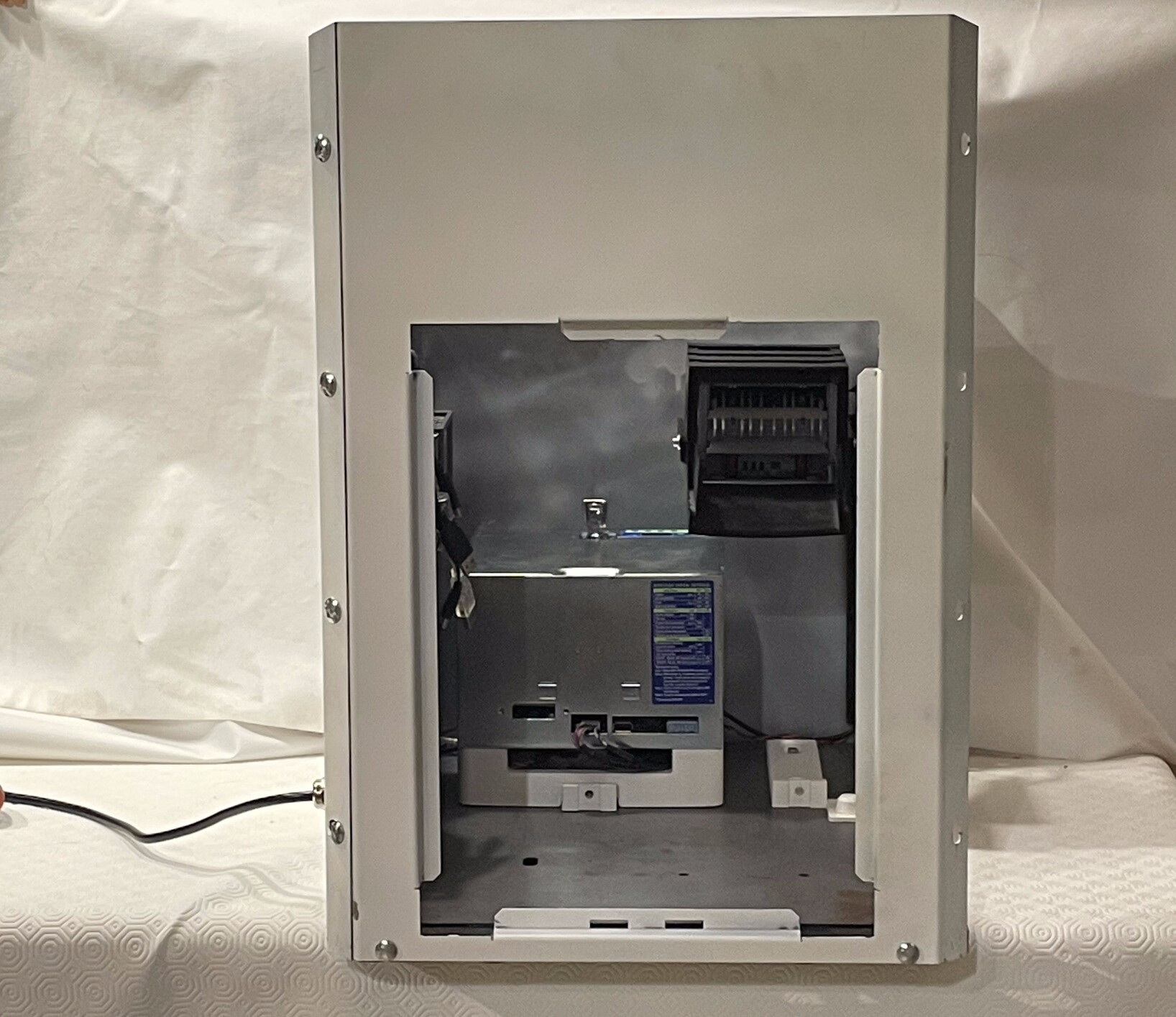
Mount back to Swapbox
| Qty | Part ID | Part description |
|---|---|---|
| 1 | Swapbox | |
| 1 | H_BP | |
| 6 | B_CB_M6_10 | |
| 6 | B_W_M6 | |
| 6 | B_N_M6 |
- Move Swapbox so that the back side of the swapbox protrudes in order to access the underside of the back of the swapbox.
- Attach H_BP to H_BS using 2x B_CB_M6_10, 2x B_W_M6, 2x B_N_M6.
- Attach H_BP to H_RP using 4x B_CB_M6_10, 4x B_W_M6, 4x B_N_M6.
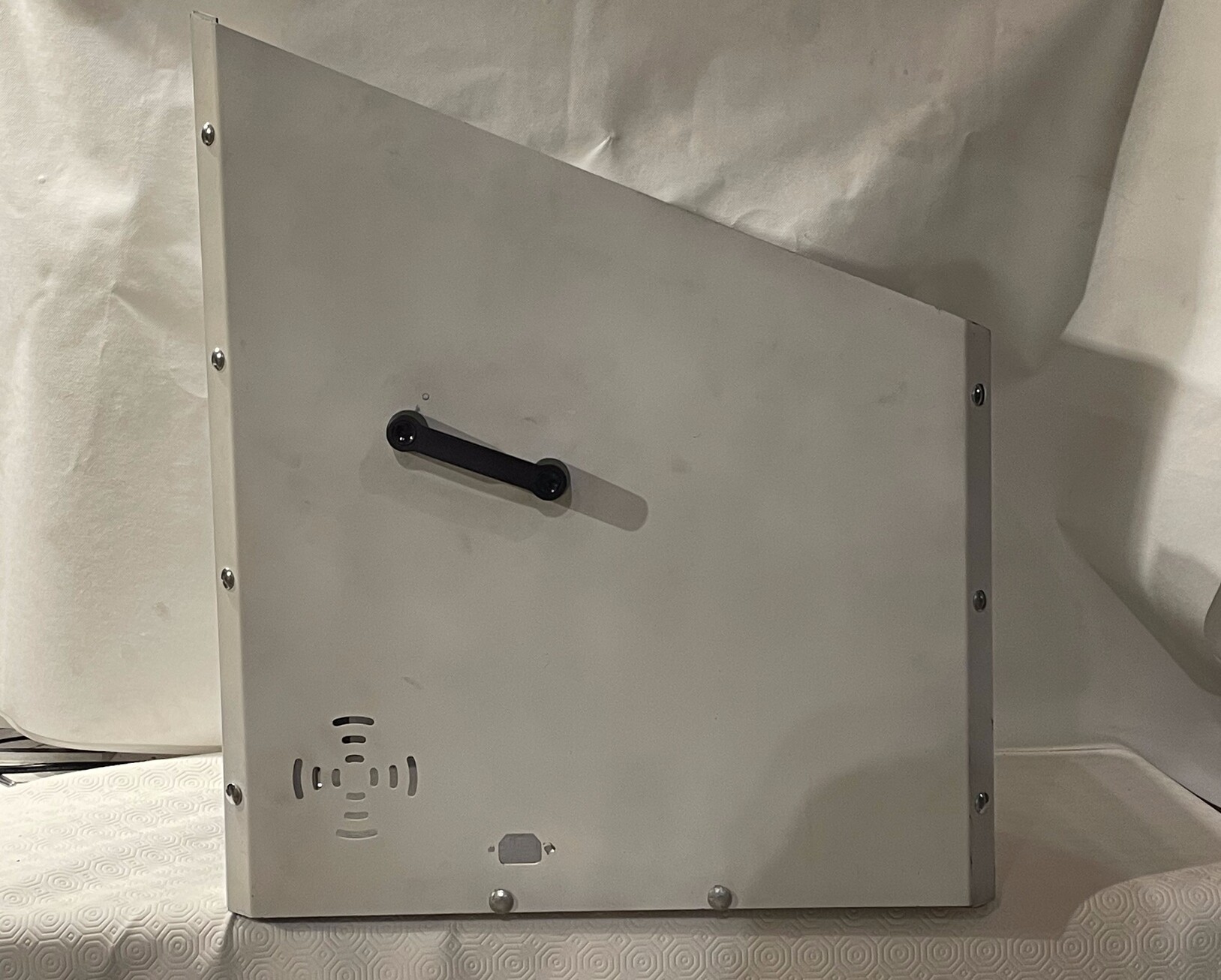
Mount left to Swapbox
| Qty | Part ID | Part description |
|---|---|---|
| 1 | Swapbox | |
| 1 | Left component | |
| 7 | B_CB_M6_10 | |
| 2 | B_CB_M6_20 | |
| 9 | B_W_M6 | |
| 9 | B_N_M6 |
- Move Swapbox so that the left side of the swapbox protrudes in order to access the underside of the back of the swapbox.
- Attach Left component to H_BS with 2x B_CB_M6_20, 2x B_W_M6, 2x B_N_M6.
- Attach Left component to H_FP with 3x B_CB_M6_10, 3x B_W_M6, 3x B_N_M6.
- Attach Left component to H_BP with 4x B_CB_M6_10, 4x B_W_M6, 4x B_N_M6.
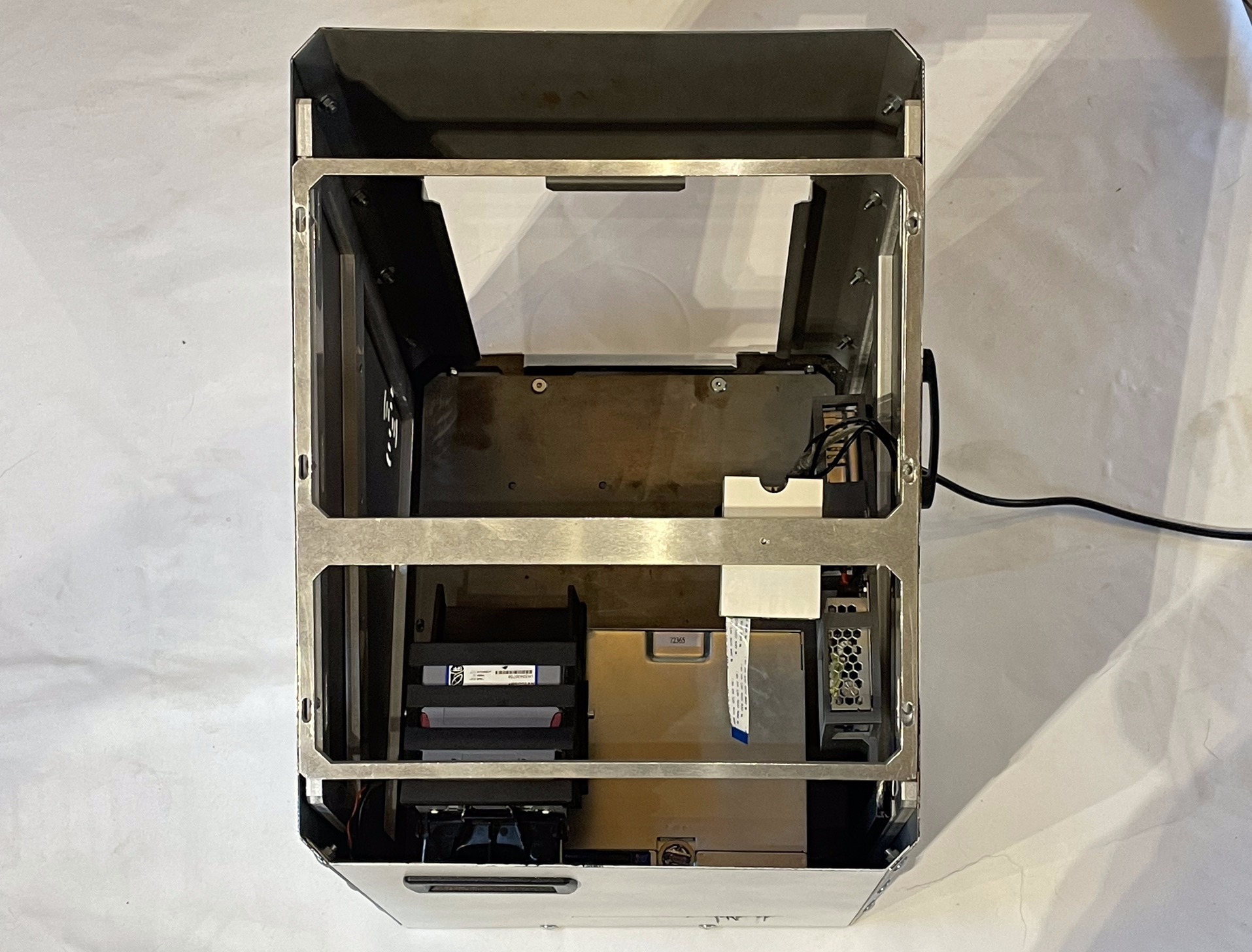
Closing the box
| Qty | Part ID | Part description |
|---|---|---|
| 1 | Swapbox | |
| 1 | Top structure component | |
| 1 | Top panel component | |
| 1 | C_SD | |
| 1 | C_ST | |
| 6 | B_CB_M6_30 | |
| 6 | B_NUT_M6 | |
| 6 | B_WASH |
- Tighten all the nuts used to attach panels together.
Mount top to Swapbox
Top structure component
- Position Top structure component on top of Swapbox. P_RC must be at the bottom right when looking from the top of the Swapbox.
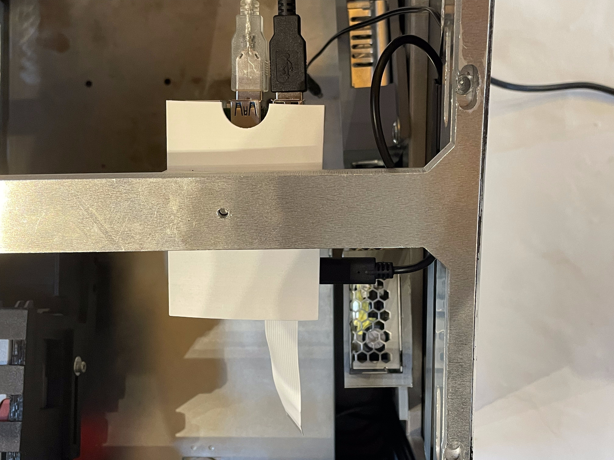
- Plug C_OA and C_ID to USB-A ports on E_RPI.
- Plug C_RP into USB-C port on E_RPI.
- Plug C_SD into the mini HDMI port on E_RPI.
- Plug C_ST into the mini USB port on E_RPI.
Top panel component
- Attach the Top panel component to the Swapbox using 6x B_CB_M6_30, 6x B_NUT_M6 and 6x B_WASH.
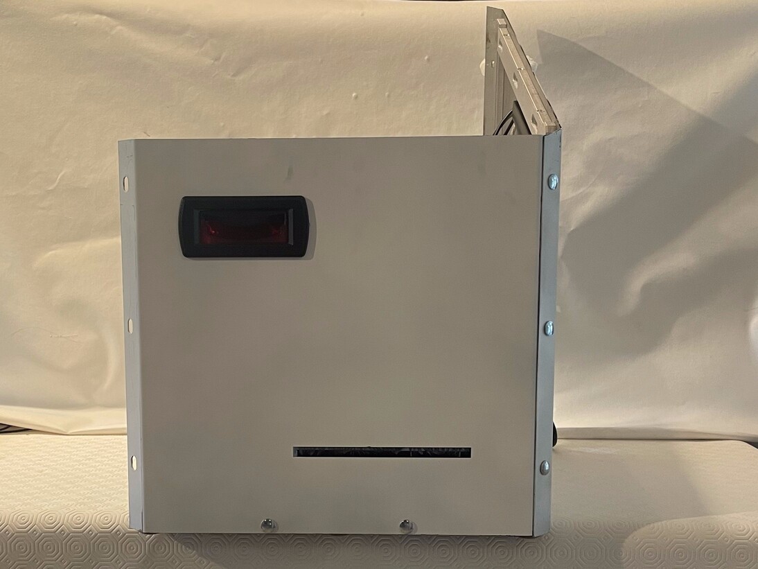
First start
- Plug the power cable of your Swapbox in a 220V wall socket.
- E_SCR should light up.
- E_COU should make a noise.
- If everything is working correctly, you can jump to Software installation section.